
User's Manual


M590 GPRS Module Hardware User Guide
Copyright © Neoway Technology Co., Ltd
15
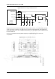
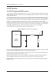
In Figure 3-13, INPUT is connected to UTXD of the MCU and VCC_IN is connected to the 5 V power
supply of the MCU. OUTPUT is connected to URXD of the module and VCC_OUT is connected to
VDD_EXT(2.8V) of the module.If the circuit is far away from the VDD_EXTpin, add a 0.1 μF decoupling
capacitor to VCC_OUT.
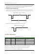
Level shifting between URXD of the MCU and UTXD of the module can be implemented in the same way.
The pull-up resistor R3 ranges from 4.7 K to 10 K; R2 ranges from 2 K to 10 K.Resistors are selected based
on the voltage of the power supply and UART baudrate. You can select resistors with great resistance to
reduce the power consumption when the power supply has great voltage or the baudrate is low. But, the
resistance will affect the quality of the square wave.In addition, the circuit performance is affected by the
signal traces during PCB layout.
It is recommended that you choose a high-speed NPN transistor because the Q1 switch rate will affect the
wave quality after level shifting.MMBT3904 or MMBT2222 is recommended.
Avoid data produced at UART when the module is powered on. You are advised to send data to the UART
3 seconds after the module is powered on so that the module would not respond wrongly.
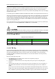
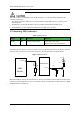
3.3 DTR and RING
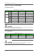
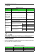
Table 3-3 DTR and RING pins
Signal I/O Function Remarks
DTR DI Signal for controlling sleep mode Left disconnected if not used
RING DO Ring output Left disconnected if not used
3.3.1 DTR Pin
Generally DTR is used for sleep mode control. It works with AT commands. For details, see M590GPRS
Module AT CommandSet.Based on the setting of the selected mode, pulling DTR low will bring the module
into sleep mode. In this mode, the idle current is less than 2 mA, the module can also respond to the
incoming call, SMS, and GPRS data.The host MCU can also control the module to exit sleep mode by
controlling DTR.
Process of entering the sleep mode:
1. Keep DTR high level in working mode. Activate the sleep mode by using the
AT+ENPWRSAVE=1command.
2. Pull DTR low, and the module will enter sleep mode, but only after process and pending data
finished.
3. In sleep mode, the module can be woken up by the events of incoming voice call, received data, or
SMS. Meanwhile the module will send out the unsolicited messages by the interface of RING or
UART.
Upon receipt of the unsolicited messages, the host MCU should pull DTR high firstly, otherwise the
module will resume sleep mode shortly. And then the host MCU can process the voice call, received
data, or SMS.After processing is finished, pull DTR low again to put the module into sleep mode.