
User's Manual

M590 GPRS Module Hardware User Guide
Copyright © Neoway Technology Co., Ltd
14
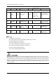
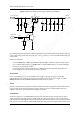
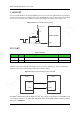
If the UART is interfacing with a MCU that has 3.3V logic levels, it is recommended that you add a level
shifting circuit outside of the module.
Figure 3-12 Recommended circuit for the communication between 3.3V MCU and UART
In Figure 3-12, 100 pF filter capacitor should be placed near the receive pin of the module. Resistance (200
Ω to 470 Ω) and capacity (100 pF to 470 pF) can be selected based on the tested signal wave. Great serial
resistance and filter capacity will decrease the signal level, resulting in great signal wave distortion and the
low adaptable UART communication baudrate. RB521S-30TE-61, RB521SM-30GJT2R, and
LRB521S-30T1G are recommended for separating diode.
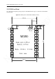
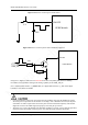
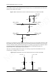
When the external MCU adopts 5 V IO system, level shifting is required for both UART receive and
transmit.Figure 3-13shows a reference circuit.
Figure 3-13 Recommended circuit for the communication between 5V MCU and UART
Module_URXD
Module_UTXD
VDD_EXT
0.1 uF
47K
RB521S
200
33 pF
33 pF
MCU_UTXD
MCU_URXD
INPUT
OUTPUT
VCC_IN VCC_OUT
4.7K 10K
Q1
R2 R3