
User's Manual

M590 GPRS Module Hardware User Guide
Copyright © Neoway Technology Co., Ltd
10
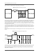
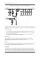
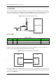
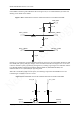
separated power supplies.The module shall be supplied by an independent power, like a DC/DC or LDO.
See Figure 3-5.
DC/DC or LDO should output rated peak current larger than 2 A.
The inductor used in Reference Design (b), should be a power inductor and have a very low resistance. 10
uH with average current ability greater than 1.2A and low DC resistance is recommended.
Figure 3-5 Reference designs of separated power supply
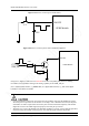
Never use a diode to make the drop voltage between a higher input and module power. Otherwise,
Neoway will not provide warranty for product issues caused by this. In this situation, the diode will
obviously decrease the module performances, or result in unexpected restarts, due to the forward voltage
of diode will vary greatly in different temperature and current.
EMC Considerations
Place transient overvoltage protection components like TVS diode on power supply, to absorb the power
surges. SMAJ5.0A/C could be a choice.
3.1.2 VDD_EXT
It is recommended that VDD_EXT is only used for interface level transformation. VDD_EXT can output
2.8 V and 50 mA. It stops output after the module is shut down.
3.1.3 Power-On/OffControl and Procedure
Prior to turning on the module, power on the host MCU and finish the UART initialization.Otherwise
conflictions may occur during initialization, due to unstable conditions.
ON/OFF is a low level pulse active input, used to turn on or off the module.
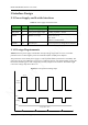
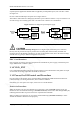
Power-On Procedure
While the module is off, drive the ON/OFF pin to ground for at least 1.2 second and then release, the
module will start. An unsolicited message (+MODEM:STARTUP) will be sent to host through UART port,
indicating that the module is powered on and can respond to AT commands.
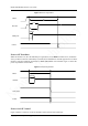
When you design your program, you can use the unsolicited message (MODEM:STARTUP) to check
whether the module is started or reset improperly.