
User's Manual

M590 GPRS Module Hardware User Guide
Copyright © Neoway Technology Co., Ltd
7
3 Interface Design
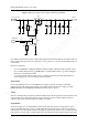
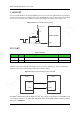
3.1 Power Supply and Switch Interfaces
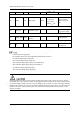
Table 3-1 Power supply and switch interface
Signal I/O Function Remarks
VBAT P Main power supply input 3.5 V to 4.3 V (3.9 V is recommended)
VDD_EXT P 2.8 V power supply output Loading capability < 50 mA
RESET DI Module reset input Reset at low level
Min. 50 ms
100 ms is recommended
ON/OFF DI On/Off input Low level pulse can change the On/Off state.
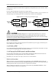
3.1.1 Design Requirements
VBAT is the main power supply of the module. Its input voltage ranges from 3.5 V to 4.3 V and the
preferable value is 3.9V.It supplies power for baseband controller and RF power amplifier.
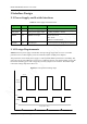
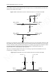
The performance of the VBAT power supply is a critical path to module's performance and stability. The
peak input current at the VBAT pin can be up to 2 A when the signal is weak and the module works at the
maximum transmitting power. The voltage will encounter a drop in such a situation. The module might
restart if the voltage drops lower than 3.5 V.
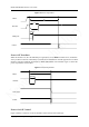
Figure 3-1 Current peaks and voltage drops
Keep above 3.5 V
Keep above 3.5 V
3.5 V
3.5 V
0 ms
0 ms
3.7 ms
3.7 ms
7.4 ms
7.4 ms
10.7 ms
10.7 ms
T
T
2.0 A
2.0 A
Voltage
Voltage
Input
Current
Input
Current
3.9 V
3.9 V