
User's Manual

M590 GPRS Module Hardware User Guide
Copyright © Neoway Technology Co., Ltd
5
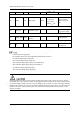
2.38<V
OH
<2.8
SMS and Incoming Call Ring
10 RING DO Ring output I/PD
0<V
IL
<0.6
2.1<V
IH
<3.1
0<V
OL
<0.42
2.38<V
OH
<2.8
Detect incoming
SMS messages or
calls
ADCDetecting
16 ADC_IN AI 10-bitADC input
Detectable voltage
range: 0 V to 2.8 V
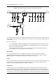
GPRS Antenna
21 GPRS_ANT
AI/O
GPRS antenna
interface
50 Ω impedance
Reserved Pins
17 NC
Must be left
disconnected.
P: indicates power supply pins
NC: indicates pins that are not supported and must not be connected
DI: indicates digital signal input pins
DO: indicates digital signal output pins
I/PD: indicates digital signal input pins with pull-down
I/PU: indicates digital signal input pins with pull-up
AI: indicates analogy signal input pins
AO: indicates analogy signal output pins
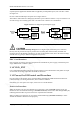
The maximum input voltage at all IO ports (including peak signal current) cannot exceed 3.1 V because
the module uses a 2.8 V IO power system. In the application of the module, the IO output voltage from the
3.3 V power supply system of the external circuit might greatly overshoot 3.1 V due to the signal integrity
design. In this situation, the IO pins of the module might be damaged if the IO signals are connected to the
IO port on the 2.8-V system. To rectify this issue, take measures to match the level. For details, see the
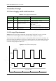
Section 3.2 UART.