
User's Manual

M590 GPRS Module Hardware User Guide
Copyright © Neoway Technology Co., Ltd
4
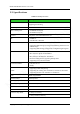
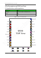
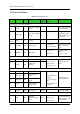
2.2 Pin Definition
Table 2-1 M590 pin definition
Pin Name I/O Function
Reset
Status
Level Feature
(V)
Remarks
Power Supply and Switch Interfaces
2, 3 VBAT P
Main power supply
input
3.5 V to 4.3 V (3.9 V
is recommended)
6 VDD_EXT P
2.8 V power supply
output
Supply power for IO
level shifting circuit.
Load capability: less
than 50 mA
1, 4,
15, 20
GND P Ground
19 ON/OFF DI On/Off input
0<V
IL
<0.6
2.1<V
IH
<VBAT
Low level pulse can
change the On/Off
state.
18 RESET DI Reset input
0<V
IL
<0.6
2.1<V
IH
<3.1
Internally pulled up
to 2.8V
Low level reset
UART Interface
7 URXD DI UART data receive
I/PU 0<V
IL
<0.6
2.1<V
IH
<3.1
0<V
OL
<0.42
2.38<V
OH
<2.8
With 47K pull-up
inside
8
UTXD DO
UART data
transmit
SIM Card
11 SIM_DATA
DI/O
SIM card data IO
0<V
IL
<0.25*VSI
M
,
0.75*VSIM<V
IH
<VSIM
0<V
OL
<0.15*VS
IM
0.85*VSIM<V
OH
<VSIM
Compatible with
1.8/3.0 V SIM card
12 SIM_CLK DO
SIM card clock
output
13 SIM_RST DO
SIM card reset
output
14 VSIM P
SIM card power
supply output
LED Indicators
5 LIGHT DO Status LED I/PD
2.8 V/4 mA output
Sleep Mode Controlling
9 DTR DI
Signal for
controlling sleep
mode
I/PD
0<V
IL
<0.6
2.1<V
IH
<3.1
0<V
OL
<0.42
Low level by default
Used together with
AT commands