
User's Manual

Shenzhen Neoway Technology Co., Ltd. Page 27 of 32
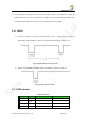
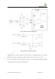
If the trace between the module and connector has to be longer, or built-in antenna is used, a π-type
matching circuit should be needed, as shown in Figure 22. The types and values of C1, L1, and L2
should be verified by testing using network analyzer instrument. If the characteristic impedance is
well matched, and VSWR requirement is met, just use a 0Ω resistor for C1 and leave L1, L2
un-installed.
Avoid any other traces crossing the antenna trace on neighboring layer.
Figure 22 Reference design for antenna interface
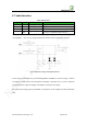
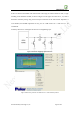
Figure 23 Reference parameters for 50Ω trace on a 1.6mm double layer PCB