
User's Manual

Shenzhen Neoway Technology Co., Ltd. Page 17 of 32
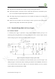
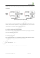
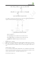
Figure 10 Reference circuit for ON/OFF control
Reference Components:
Q1: MMBT3904, or to use digital transistor with bias resistors built in, like DTC123/114
The combination of R3 and R4, should limit the high voltage of ON/OFF less than 3.0V.
Note:
If the host itself is not initialized before turning on the module, some abnormal conditions on
IO or UART may affect the power on procedure.
The better way to rescue the module from abnormal condition, is to apply a power OFF-ON
procedure, rather than using the ON/OFF control signal. In fact ON/OFF signal is
software-dependent.
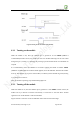
6.2.3 RESET
Pull the RESET signal to low level for at least 60mS to reset the module. A pull-up resistor is
internally included. Reset pin can be left open if not used.
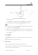
6.2.4 VCCIO
VCCIO is provided to power the level translators, with a 2.8V / 5mA output.
VCCIO can also be used to monitor the on/off state of module. It outputs 2.8V high level while the
module is on, and low level while the module is off.