
User's Manual
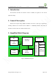
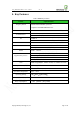
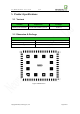
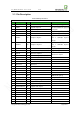
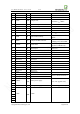
Table Of Contents
- 1. Introduction
- 2. General Description
- 3. Simplified Block Diagram
- 4. Key Features
- 5. Product Specifications
- 6. Application Interface
- 7. Mounting the Module onto the Application Board
- 8. Package
- 9. Terms and Abbreviations

Neo_M680 Hardware User Guide V1.0
Copyright Neoway Techlology Co., Ltd. Page 9 of 31
5.3 Pin Description
Table2 M680 pin definition
M680
Pin Signal I/O Function Note
1 ON/OFF DI Switch the module on/off Low level pulse triggered
2 SPKP AO Speaker output P
Use AT command to open and
0.9W@8Ω
3 SPKN AO Speaker output N
4
MICP0
AI
MIC+
Vi ≤ 200mVpp
5
MICN0
AI
MIC-
Vi ≤ 200mVpp
6
EAR-L
AO
Earpiece output L
Signal Ended Output. Can
drive a 16Ω/32Ω earpiece
directly.
7
EAR-R
AO
Earpiece output R
Signal Ended Output. Can
drive a 16Ω/32Ω earpiece
directly.
8
MICN1
AI
MIC-
Vi ≤ 200mVpp
9
MICP1
AI
MIC+
Vi ≤ 200mVpp
10 RECN AO Receiver output N
32Ω receiver output
11 RECP AO Receiver output P
12 Reserved Reserved
13 Reserved Reserved
14 Reserved Reserved
15 Reserved Reserved
16 Reserved Reserved
17 Reserved Reserved
18 GND PWR GND
19
SIM_CLK
DO
SIM clock
20
SIM_DATA
DIO
SIM data
5KΩ internal pull-up
21 SIM_RST DO SIM reset Prompted by module
22 VSIM
PWR
SIM supply voltage 1.8/3.0V compatible.
23 DAISYNC DO Digital audio synchronization
24 DAIPCMIN DI Digital audio input
25 DAIPCMOUT DO Digital audio output
26 DAICLK DO Digital audio signal clock
27 Reserved Reserved
28 Reserved Reserved
29 GND PWR GND
30 BT_ANT I/O Antenna interface for BT Connect 50Ω antenna
31 GND PWR GND
32 Reserved Reserved