
User's Manual
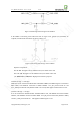
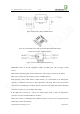
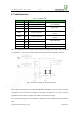
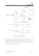
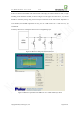
Table Of Contents
- 1. Introduction
- 2. General Description
- 3. Simplified Block Diagram
- 4. Key Features
- 5. Product Specifications
- 6. Application Interface
- 7. Mounting the Module onto the Application Board
- 8. Package
- 9. Terms and Abbreviations

Neo_M680 Hardware User Guide V1.0
Copyright Neoway Techlology Co., Ltd. Page 26 of 31
6.7 Audio Interface
Table 7 Audio Interface
Signal I/O Function Note
SPKP AO Speaker output P
Use AT command to open
and 0.9W@8Ω
SPKN AO Speaker output N
MICP0
AI
MIC+ input
Vpp≤ 200mV
MICN0
AI
MIC- input
EAR-L
AO
Earpiece output L
Can drive a 16Ω/32Ω earpiece
directly
EAR-R
AO
Earpiece output R
Can drive a 16Ω/32Ω earpiece
directly
MICN1
AI
MIC-
Vpp≤ 200mVpp
MICP1
AI
MIC+
RECN AO Receiver output N 32Ω receiver output
RECP AO Receiver output P 32Ω receiver output
For reference audio interface see Figure 18. The peak-peak voltage routed to MIC+/MIC- should not
exceed 200mV. AGC circuit is integrated inside the module. Electret microphone is suited.
Figure 18 Reference design of microphone interface
A bias voltage for microphone is provided through MICP and MICN, as shown in Figure 19. But if
an amplifier is used between the microphone and module, capacitors like C1 and C2, should be
placed between the outputs of amplifier and module, to block the bias voltage.
For a peak-peak voltage greater than 200mV, an attenuation circuit comprised of R1-R4 should be
used.