
User's Manual
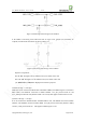
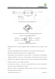
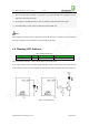
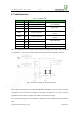
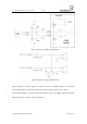
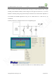
Table Of Contents
- 1. Introduction
- 2. General Description
- 3. Simplified Block Diagram
- 4. Key Features
- 5. Product Specifications
- 6. Application Interface
- 7. Mounting the Module onto the Application Board
- 8. Package
- 9. Terms and Abbreviations

Neo_M680 Hardware User Guide V1.0
Copyright Neoway Techlology Co., Ltd. Page 25 of 31
☆
The antenna should be installed a long distance away from the SIM card and SIM card traces,
especially to the build-in antenna.
☆
The PCB traces of SIM should be as short as possible and shielded with GND copper.
☆
The ESD diodes or small capacitors should be closed to SIM card.
Note:
Small capacitors and the junction capacitance of the ESD diode are to avoid the interference from/to
antenna, ensuring the correct SIM access and good RF performance.
6.6 Running LED Indicator
Table 6 Running Indicator
Signal I/O Function Note
BACK_LIGHT DO Running Status Can drive a LED directly
The various blink behaviors of LED indicate different of module status.
It can output a 4mA current and 2.8V voltage, therefore a LED can be directly connected to this pin
with a resistor in series. For better luminance, drive the LED with a transistor instead, see Figure 17.
Figure 17 LED Indicator