
User's Manual
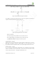
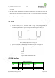
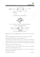
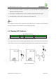
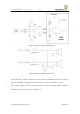
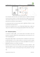
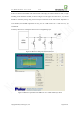
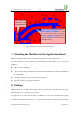
Table Of Contents
- 1. Introduction
- 2. General Description
- 3. Simplified Block Diagram
- 4. Key Features
- 5. Product Specifications
- 6. Application Interface
- 7. Mounting the Module onto the Application Board
- 8. Package
- 9. Terms and Abbreviations

Neo_M680 Hardware User Guide V1.0
Copyright Neoway Techlology Co., Ltd. Page 21 of 31
Figure 12 Interfacing with 3.3V logic levels of MCU
If the UART is interfacing with a MCU that has 5V logic levels, general level translators are
required, for both inputs and outputs. As shown in Figure 13.
Figure 13 Interfacing with 5V logic levels of MCU
Reference components:
R2: 2K-10K. The higher rate the UART works at, the smaller value used
R3: 4.7K-10K. The higher rate the UART works at, the smaller value used
Q1: MMBT3904 or MMBT2222. High-speed transistors preferred.
Used for 5V logic -> 2.8V logic:
While this circuit used between MCU TXD and module URXD1, the INPUT signal is connected to
MCU TXD, and OUTPUT connected to module URXD1. VCC_IN powered from 5V and
VCC_OUT powered from 2.8V (module’s VMC can be used). This applies to DTR control as well.
Used for 2.8V logic -> 5V logic:
It can be used between module UTXD1 and MCU RXD as well, with INPUT connected to module
UTXD1, and OUTPUT connected to MCU RXD. VCC_IN powered from 2.8V (module’s VMC)
and VCC_OUT powered from 5V. This applies to RING signal as well.