
User's Manual
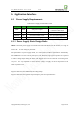
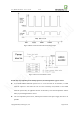
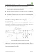
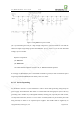
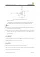
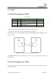
Table Of Contents
- 1. Introduction
- 2. General Description
- 3. Simplified Block Diagram
- 4. Key Features
- 5. Product Specifications
- 6. Application Interface
- 7. Mounting the Module onto the Application Board
- 8. Package
- 9. Terms and Abbreviations

Neo_M680 Hardware User Guide V1.0
Copyright Neoway Techlology Co., Ltd. Page 20 of 31
6.3 UART
6.3.1 Basic Descriptions of UART
Table 4 UART
Signal
I/O
Function
Note
URXD1 DI Serial input of module
UTXD1
DO
Serial output of module
DTR
DI
Signal for controlling sleep mode
RING
DO
Ringing output
UART1 is for AT commands, data sending/receiving, firmware updating, etc.
As a DCE device, the module is connected to DTE as shown in Figure 11.
Supported baud rates are 1200, 2400, 4800, 9600, 19200, 38400, 57600, 115200, 230400bps, and the
default is 115200.
Figure 11 Connection between DCE (module) and DTE
The UART of M680 works at 2.8V CMOS logic level. The voltages for input high level should not
exceed 3.0V.
6.3.2 Level Translators for UART
If the UART is interfacing with a MCU that has 3.3V logic levels, resistors should be connected in
series with the signals.