
User's Manual
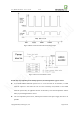
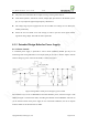
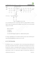
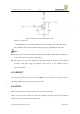
Table Of Contents
- 1. Introduction
- 2. General Description
- 3. Simplified Block Diagram
- 4. Key Features
- 5. Product Specifications
- 6. Application Interface
- 7. Mounting the Module onto the Application Board
- 8. Package
- 9. Terms and Abbreviations

Neo_M680 Hardware User Guide V1.0
Copyright Neoway Techlology Co., Ltd. Page 15 of 31
The power source should be able to output an average current greater than 1A.
Some small capacitors, with values of 0.1uF, 100pF, 33pF, placed close to the module’s power
pin, are very helpful to suppress high frequency disturbances.
The voltage range of power supply must never be exceeded. Over-voltage can even destroy the
module permanently.
Ensure the trace for VBAT to be wide enough, in order to pass the current peaks without
significant voltage drops. The width of 2mm is preferable.
6.1.2 Extended Design Rules for Power Supply:
6.1.2.1 Power Control
A controlled power supply is preferable if used in harsh conditions. RESET pin may be not
functioning under strong disturbance. The output enable pin of LDO or DC/DC chipset could be
used for emergency power control of the module, as shown in Figure 6.
Figure 6 Using LDO’s enable pin for emergency power control
The alternative way is to use a P-MOSFET to control the module’s power, as shown in Figure 7. The
GPRS_EN signal is routed to host GPIO, controlling the ON/OFF of the P-MOSFET. The host can
cut off and then switch on the power supply in case of abnormal conditions, such as no response
from the module or the disconnection of GPRS.