
User's Manual
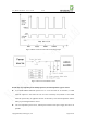
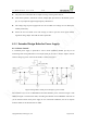
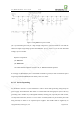
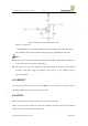
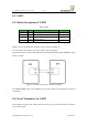
Table Of Contents
- 1. Introduction
- 2. General Description
- 3. Simplified Block Diagram
- 4. Key Features
- 5. Product Specifications
- 6. Application Interface
- 7. Mounting the Module onto the Application Board
- 8. Package
- 9. Terms and Abbreviations

Neo_M680 Hardware User Guide V1.0
Copyright Neoway Techlology Co., Ltd. Page 13 of 31
6. Application Interface
6.1 Power Supply Requirements
Table3 Power Supply and ON/OFF Control
Signal I/O Function Note
VMC PWR 2.8V power output
Can be used to power the level
translators. Imax=5mA
Reset DI Reset input Active low > 60mS.
ON/OFF DI Switch the module on/off Low level pulse triggered.
VBAT
PWR
Main Power Supply
3.5V~4.3V(typical 3.9V)
6.1.1 Power Supply Basic Design Rules
VBAT is the main power supply for internal base band and radio PA of the module, in a range of
3.5V-4.3V. A 3.9V voltage is preferable.
The performance of power supply issued, is a critical path to module’s performance and stability.
The GSM bursts can cause current peaks up to 1.8A, therefore large bypass capacitors are expected
to reduce voltage drops during the bursts. The biggest current occurs when the received signal is
very low. It’s very important to ensure that the voltage of supply rail never drops below 3.5V
while any burst occurs.
Figure 4 shows how the GSM bursts and voltage drops.
Figure 5 shows how the capacitor helps to improve peak current performance: