
User's Manual
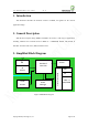
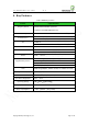
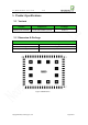
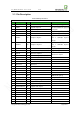
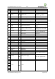
Table Of Contents
- 1. Introduction
- 2. General Description
- 3. Simplified Block Diagram
- 4. Key Features
- 5. Product Specifications
- 6. Application Interface
- 7. Mounting the Module onto the Application Board
- 8. Package
- 9. Terms and Abbreviations

Neo_M680 Hardware User Guide V1.0
Copyright Neoway Techlology Co., Ltd. Page 10 of 31
33 Reserved Reserved
34 Reserved Reserved
35 Reserved Reserved
36 VMC PWR Output 2.8V
Can be used to power the level
translators. I
max
=50mA
37 URXD DI Serial data input of module
38
UTXD
DO
Serial data output of module
39 Reserved Reserved
40 Reserved Reserved
41
VRTC
PWR
RTC power
2.8V, I
max
=2mA
42 DTR DI Data Terminal Ready
Can be used to control sleep
mode.
43 RING DO Output for RING indicator
Can be used to indicate an
incoming voice call or SMS.
44
LIGHT
DO Status LED
2.8V/4mA output
Can drive a LED directly
45
Reset
DI Reset input Active low
46 GND PWR GND
47
GPRS_ANT
I/O GPRS antenna interface Connect 50Ω antenna
48 GND PWR GND
49 Reserved Reserved
50 Reserved Reserved
51 Reserved Reserved
52 Reserved Reserved
53 Reserved Reserved
54 Reserved Reserved
55 Reserved Reserved
56
ADC
AI
ADC input
0V<Vin<2.8V
61
USB_DM
I/O
Software download interface
62
USB_DP
I/O
57
VBAT
PWR
Main power supply
3.5V~4.3V (typical 3.9V)
58
59
68
VBAT
PWR
Main power supply
3.5V~4.3V (typical 3.9V)
60
GND
PWR
GND
63
64
65
66
67
69