
User's Manual

Neo_M6
60 User Manual V1.0
All
rights reserved by Shenzhen Neoway Technology Co., Ltd Page 9 Total 11
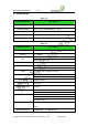
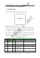
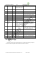
earp
hone audio output
9
EARN AO Negative electrode of
earphone audio output
32Ω earphone driving output
10
DTR DO Low power consumption
set
11 GND
PWR Grand
12 RING
DI Ring output
13 VCCIO
PWR 2.8V output Can be supplied to IO level shift
circuit, loading capacity < 50mA
14 Reserved
Reserved
15 Reserved
Reserved
16
URXD DI UART data receiving
17
UTXD DO UART data transmitting
Used to GPRS communications
and AT commands
18 GND
PWR Grand
19 Res
et DI Reset
Soft reset input, low level reset
20 BACK_LIG
HT
DO Working
station
indicator, output square
signal of 0.5s high level,
1.5s low level
High level light LED,need to
parallel connect a capacitor of
0.1uF
21
ON/OFF DI ON/OFF input low level pulse can change
ON/OFF state, need to keep high
level,Refer to chapter 6.1.3
22
ANT I/O GPS antenna RF
interface
23 GND
PWR Grand
24 GND
PWR Grand
25 GND
PWR Grand
26 VBAT
PWR Main Power
3.5V~4.3V,recommend 3.9V
27 VBAT
PWR Main Power
3.5V~4.3V,recommend 3.9V
28 GND
PWR Grand
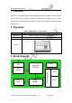
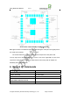
5.2 PCB Packaging
The signal connection us
e 74pin SMD pad.The pin is stamp hole(half hole).The pitch is
1.27mm.The PCB encapsulation we recommend is as chart 5-1.Unit:mm
All
rights reserved by Shenzhen Neoway Technology Co., Ltd Page 9 Total 12