
User's Manual

Neo_M6
60 User Manual V1.0
All
rights reserved by Shenzhen Neoway Technology Co., Ltd Page 8 Total 11
5
Pin Definition & Encapsulation
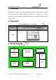
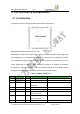
5.1 Pin
Definition
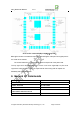
The signal connection uses 28pin SMD p
ad of stamp hole(half hole).
Note: M660
module IO interface level is 2.8V.
Because the module IO uses 2.8V power supply system, the maximum input voltage of all
the IO interface can not exceed the maximum 3.3V, otherwise it may damage the module
IO. Considering the signal integrality designing reasons,while the external circuit use 3.3V
power system the IO interface output voltage will exceed 3.3V because of overshoot
phenomenon, sometimes can even reach 3.5V.Therefore,the IO pin of the module will be
damaged if 3.3V IO signal is connected to 2.8V IO of the module directly.
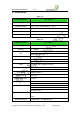
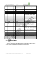
Table 5-1 M660 Pin Definition
Pin
Signal Name
I/O Function
De
scription
Rem
ark
1 VSIM
PWR Main Power Compatible to 1.8/3.0V SIM card
2
SIM_CLK DO Clock of SIM card
3
SIM_DATA DIO Data input & output of
SIM card
Built-in 5K pull-up resistor
4 GND
PWR GRAND
5 SIM_RST
DO SIM card reset
6
MICP AI Positive electrode of
MIC audio input
Alternating peak voltage≤200mV
7
MICN AI Negative electrode of
MIC audio input
Alternating peak voltage≤200mV
8
EARP AO Positive electrode of 32Ω earphone driving output
All
rights reserved by Shenzhen Neoway Technology Co., Ltd Page 8 Total 12