
User's Manual
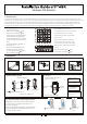

3.8 Perform motion test to the detect ion area: install th e cover and close thefasten part (refer to the
right diagram)
1. Start the test at least 2 minutes after power supply
2. Crossing to any direction of the detection area, your walking with 0.75m/s will cause the LED indicator
to light for 2-3 seconds (refer to the right diagram)
3 .Perform motion test from contrary directions in order to confirm the boundary of two sides. Make
confirmed that detection center pointing to the center of protected area.
4. Away from the detector 3 to 6 m, raise slowly your arm and reach into the detection zone, mark the lower
limit of PIR detection. Do the same step to confirm the upper limit.
5.the center of detection zone should not uphill incline. To obtain a good detection range , please adjust the
vertical detection range, en-sure the detector is in a correct position.
6. After MW sensitivity or detection angle are adjusted, walking test must be performed according to the
above steps.
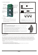
3.4 Fanction explanation:
Solar board
connector
Green LED
Pretrigger LED
Anti-strong
light switch
Battery
connector
Trigger pluse
choose jumper
switch
Trigger pluse
choose jumper
switch 1
Tamper switch
Wiring terminal
Red LED
alarm LED
3.5 Function of jumper switch:
Trigger pluse count,choose jumper switch 1,
accroding to infrnred sensor 1
3.6 Wiring terminal
+-
AlarmTamp
12V
PowerAlarm
Tamper
Alarm:When the external power supply for 2-10 minutes,
Alarm ouput is N/C
Alarm:When the external power disconnect about 2-10
minutes,Alarm output convert to N/O on wireless mode
One Pluse
Two Pluse
Three Pluse
Trigger pluse connt,choose jumper switch 2,
accroding to infrnred sensor 2
One Pluse Two Pluse
Three Pluse
3.7 Coding
Whenthe alarm panel enter coding mode,please press the
tamper switch of FT-89R for 3 seconds,immediately then
loose,when you can hear a hing sonnd from panel ,which
means coding successfally.
FCC WARNING
Changes or modifications not expressly approved by the party responsible for compliance could void the user's authority to operate
the equipment.
This equipment has been tested and found to comply with the limits for a Class B digital device, pursuant to Part 15 of the FCC
Rules. These limits are designed to provide reasonable protection against harmful interference in a residential installation. This
equipment generates uses and can radiate radio frequency energy and, if not installed and used in accordance with the instructions,
may cause harmful interference to radio communications. However, there is no guarantee that interference will not occur in a
particular installation. If this equipment does cause harmful interference to radio or television reception, which can be determined
by turning the equipment off and on, the user is encouraged to try to correct the interference by one or more of the following
measures:
-- Reorient or relocate the receiving antenna.
-- Increase the separation between the equipment and receiver.
-- Connect the equipment into an outlet on a circuit different from that to which the receiver is connected.
-- Consult the dealer or an experienced radio/TV technician for help
.