
User's Manual


68
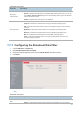
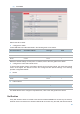
(4) Click Save.
Wait for the AP to reboot.
2. Configure the switch.
Create IEEE 802.1Q VLANs described in the following table on the switch.
Port Connected To
Accessible VLAN ID
P
ort Type
PVID
AP
1,
2, 3, and 4
Trunk
1
LAN server
3
and 4
Trunk
1
Router
2
and 4
Trunk
1
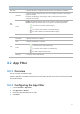
Retain the default settings of other ports. For details, refer to the user guide for the switch.
3. Configure the router and internal server.
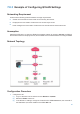
To ensure that wireless clients connected to the AP can access the internet, the router and internal
server must support the QVLAN function and configured with QVLAN settings. The following
provides configuration details.
Router
Port Connected To
Accessible VLAN ID
Port Type
PVI
D
Switch
2
and 4
Trunk
1
Internal server
Port Connected To
Accessible VLAN ID
Port Type
PVID
Switch
3
and 4
Trunk
1
For details about how to configure a required device, refer to the user guide for the device.
Verification
Verify that wireless clients connected to the wireless network internet can access only the internet,
wireless clients connected to the wireless network oa can access only the LAN, and wireless clients