User Guide =OXKRKYY 'IIKYY 6UOTZ '6 1
Copyright Statement ©2016 IP-COM Networks Co., Ltd. All rights reserved. is the registered trademark of IP-COM Networks Co., Ltd. Other brand and product names mentioned herein are trademarks or registered trademarks of their respective holders. Copyright of the whole product as integration, including its accessories and software, belongs to IP-COM Networks Co., Ltd.
Preface Thank you for choosing IP-COM! Please read this user guide before you start with AP255. Conventions The typographical elements that may be found in this document are defined as follows. Item Presentation Example Cascading menus > System > Live Users Parameter and value Bold Set User Name to Tom. Variable Italic Format: XX:XX:XX:XX:XX:XX UI control Bold On the Policy page, click the OK button. The symbols that may be found in this document are defined as follows.
Acronym or Abbreviation Full Spelling STB Set Top Box URL Uniform Resource Locator VLAN Virtual Local Area Network VPN Virtual Private Network WISP Wireless Internet Service Provider WPS WiFi Protected Setup Additional Information For more information, search this product model on our website at http://www.ip-com.com.cn. Technical Support If you need more help, contact us by any of the following means. We will be glad to assist you as soon as possible. +86-755-27653089 info@ip-com.com.
Contents Product Overview .................................................................................................................................... 1 Introduction ...................................................................................................................................... 1 Features ........................................................................................................................................... 1 Appearance .........................
Changing SSID Settings ...................................................................................................... 26 SSID Setup Example ........................................................................................................... 30 Radio .............................................................................................................................................. 47 Overview ......................................................................
Verification ........................................................................................................................... 80 Deployment .......................................................................................................................................... 81 Overview ...................................................................................................................................... 81 Configuring the Deployment Mode .....................
Product Overview Introduction AP375 provides three radio frequency (RF) bands, including one 2.4 GHz band, one 5 GHz band, and one band that be changed between 2.4 GHz and 5 GHz. These bands together offer a total wireless data rate of up to 2100 Mbps. AP375 also supports IEEE 802.3at PoE power supplies and can be managed using its own web UI or an IP-COM AP controller.
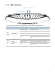
LED Indicators 8, HGTJ 2 8, HGTJ 3 System/RF band 1 The following describes the LED indicator states of the AP that has been powered on. Print SYS Radio1 Radio2 and Radio3 LED Indicator System/RF band 1 LED indicator RF band 2 LED indicator RF band 3 LED indicator Description Solid on in orange The system is booting. Solid on in green RF band 1 is enabled. Blinking in green RF band 1 is transmitting or receiving data.
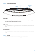
Ports and Button PoE VUXZ 8KYKZ H[ZZUT LAN port PoE port This 10/100/1000 Mbps auto-negotiation port is used to connect to a PoE power supply and exchange data. To supply power to the AP, use an Ethernet cable to connect the AP to an injector or a PoE switch compliant with the IEEE 802.3at standard. LAN port This 10/100/1000 Mbps auto-negotiation port is used to connect to switches, computers and other devices.
Label The label is described as follows: (1): Default IP address of the AP. You can use this IP address to log in to the web UI of the AP. (2): Default user name and password of the web UI of the AP.
Managing the AP The AP can be managed using the web UI of the AP or an IP-COM AP controller (AC1000/AC2000/AC3000). Managing the AP using an AP controller Refer to Section 10 "Deployment Mode." For details about how to manage the AP using an AP controller, refer to the user guide for the AP controller available at www.ip-com.com.cn.
Login Logging in to the Web UI of the AP You can log in to the web UI of the AP using a web browser. The procedure is as follows: 1. Use an Ethernet cable to connect the management computer to the AP or the switch connected to the AP. 2. Set IP address of your local area connection to 192.168.0.X (X: 2 - 253) and Subnet mask to 255.255.255.0. 3. Start a web browser on the computer, enter the management IP address of the AP (default: 192.168.0.254) in the address bar, and press Enter. 4.
---End 4UZK If this page is not displayed, refer to Q1 in FAQ. You can now start configuring the AP.
Logging Out of the Web UI of the AP If you log in to the web UI of the AP and perform no operation within the login timeout interval, the AP logs you out. When you close the web browser, the system logs you out as well. Web UI Layout The web UI of the AP is composed of three parts, including the 2-level navigation tree, tab page area, and configuration area. See the following figure.
Common Buttons The following table describes the common buttons available on the web UI of the AP. Button Description Refresh It is used to update the content of the current page. Save It is used to save the configuration on the current page and enable the configuration to take effect. Restore It is used to change the current configuration on the current page back to the original configuration. Help It is used to view help information corresponding to the settings on the current page.
Quick Setup Overview This module enables you to quickly configure the AP so that wireless devices such as smart phones and pads can access the internet through the wireless network of the AP. This AP can work in AP or AP+Client mode. AP mode By default, the AP works in this mode. In this mode, the AP connects to the internet using an Ethernet cable and converts wired signals into wireless signals to provide wireless network coverage. See the following topology.
Quick Setup AP Mode 1. Choose Quick Setup. 2. Set WIFI Radio to the RF band you want to set, such as Radio 1 – 2.4 GHz. 3. Set Mode to AP Mode. 4. Change the primary SSID of the selected RF band in the SSID text box. 5. Select a security mode from the Security Mode drop-down list box and set the corresponding parameters. 6. Click Save.
Parameter Description It specifies the RF band to be configured. WIFI Radio This AP provide three RF bands. RF band 1 is a 2.4GHz band, RF band 2 is a 5 GHz band, whereas RF band 3 is a 2.4 GHz or 5 GHz band. Mode It specifies the working mode of the AP, including the AP mode and AP+Client mode. SSID It enables you to change the primary SSID of the selected RF band. Security Mode It specifies the security mode corresponding to the SSID.
7. If the wireless network of the upstream device is encrypted, set Security Key to the wireless network password of the device or set RADIUS Server, RADIUS Port, and RADIUS Password to the IP address, port number, and password of the RADIUS server. 8. Click Save. ---End After the configuration, you can select the SSID on your wireless devices such as smart phones and enter your wireless network password to connect to the wireless network of the AP and access the internet through the AP.
Status System Status The access the page, choose Status > System Status. The page displays the system and LAN port status of the AP. Parameter description Parameter Device Name Description It specifies the name of the AP. You can change the AP name on the Network > LAN Setup page or on the SNMP page. System Time It specifies the current system time of the AP. Up Time It specifies the time that has elapsed since the AP was started last time.
Parameter Description IP Address It specifies the IP address of the AP. The web UI of the AP is accessible at this IP address. Subnet Mask It specifies the subnet mask of the IP address of the AP. Primary DNS Server It specifies the primary DNS server of the AP. If it is blank, the AP does not have a primary DNS server. Secondary DNS Server It specifies the secondary DNS server of the it is blank, the AP does not have a secondary DNS server.
Parameter SSID Status Description Channel Utilization (%) It specifies the air interface usage of the current working channel. TX (%) It specifies the proportion of AP-transmitted packets in the current working channel usage. RX (%) It specifies the proportion of AP-received packets in the current working channel usage. SSID It specifies all the SSIDs corresponding to the RF band. MAC Address It specifies the physical addresses corresponding to the SSIDs.
This page displays information about the wireless clients connected to the wireless networks of the AP by RF band. By default, the page displays information about the wireless clients connected to the wireless network corresponding to the primary SSID of RF band 1 of the AP. To view the wireless client connection information of an SSID of an RF band, perform the following procedure: 1. Choose Status > Wireless Clients. 2.
Network Settings LAN Setup Overview To access the page, choose Network > LAN Setup. This page enables you to view the MAC address of the LAN port of the AP and set the name, Ethernet mode, IP obtaining method, and other related parameters of the AP. Parameter description Parameter Description It specifies the MAC address of the LAN port of the AP. MAC Address The default primary SSID of RF band 1 of the AP is IP-COM_XXXXXX, where XXXXXX indicates the last 6 characters of this MAC address.
Parameter IP Address Subnet Mask Description It specifies the IP address of the AP. The web UI of the AP is accessible at this IP address. The default IP address is 192.168.0.254. Generally, ensure that this IP address is in the same network segment as the LAN IP address of your LAN router connected to the internet, so that the AP can access the internet. It specifies the subnet mask of the IP address of the AP. The default subnet mask is 255.255.255.0. It specifies the gateway IP address of the AP.
---End If you change the IP address of the LAN port, change the IP address of your management computer as well so that the two IP addresses belong to the same network segment. Then, you can use the new IP address of the LAN port to log in to the web UI of the AP. Automatically Obtaining an IP Address This mode enables the AP to automatically obtain an IP address, subnet mask, gateway IP address, primary DNS server IP address, and secondary DNS server IP address from a DHCP server in the network.
DHCP Server Overview The AP provides a DHCP server function to assign IP addresses to clients on the LAN. By default, the DHCP server function is disabled. 4UZK If the new and original IP addresses of the LAN port belong to different network segment, the system changes the IP address pool of the DHCP server function of the AP so that the IP address pool and the new IP address of the LAN port belong to the same network segment. Configuring the DHCP Server 1.
Parameter Description It specifies the validity period of an IP address assigned by the DHCP server to a client. When the lease time expires: Lease Time − If the client is still connected to the AP, the client automatically extends the lease time and continues to use this IP address. − If the client has been shut down, the Ethernet cable between the client and the AP has been removed, or the wireless connection between the client and the AP is released, the AP recycles the IP address.
You can click Refresh to view the latest client information.
Wireless Settings SSID Setup Overview This module enables you to set SSID-related parameters of the AP. Broadcast SSID When the AP broadcasts an SSID, nearby wireless clients can detect the SSID. When this parameter is set to Disable, the AP does not broadcast the SSID and nearby wireless clients cannot detect the SSID. In this case, you need to enter the SSID manually on your wireless client if you want to connect to the wireless network corresponding to the SSID.
The WMF function of the AP converts multicast traffic into unicast traffic and forwards the traffic to the multicast traffic destination in the wireless network. This helps save wireless resources, ensure reliable transmission, and reduce delays. Maximum Clients This parameter specifies the maximum number of clients that can connect to the wireless network corresponding to an SSID. If the number is reached, the wireless network rejects new connection requests from clients.
Changing SSID Settings To change the basic settings of an SSID for an RF band, perform the following procedure: 1. Choose Wireless > SSID Setup. 2. Select the RF band corresponding to the SSID. 3. Select the SSID from the SSID drop-down list box. 4. Change the parameters as required. Generally, you only need to change the Enable, SSID, and Security Mode settings. 5. Click Save. ---End Parameter description Parameter Description It specifies the SSID to be configured.
Parameter Description SSID can communicate with each other. WMF It specifies whether to enable the WMF function. Probe Broadcast Packets Control By default, all wireless clients are detecting and scanning the nearby wireless networks using the Probe Request frame (including SSID field). After receiving the packets, the device decides whether to join the network and responds to the Probe Response (including all parameters of Beacon frame), consuming massive wireless resources.
Parameter Description corresponding to the selected SSID without being authenticated, and the data exchanged between the client and the network is encrypted in WEP security mode. − Shared: It specifies that a shared key is used for authentication and data exchanged is encrypted using WEP. In this case, a wireless client must use a preset WEP key to connect to the wireless network corresponding to an SSID of the AP.
Parameter Description Security Mode is set to WPA2-PSK or Mixed WPA/WPA2-PSK, this parameter has the AES, TKIP, and TKIP&AES values. Key Key Update Interval − AES: It indicates the Advanced Encryption Standard. − TKIP: It indicates the Temporal Key Integrity Protocol. If this encryption algorithm is used, the AP can reach a maximum wireless transmission rate of 54 Mbps. − TKIP&AES: It indicates that both TKIP and AES encryption algorithms are supported.
Parameter Description interval results in higher data security. The value 0 indicates that a WAP key is not updated. SSID Setup Example Setting up a Non-encrypted Wireless Network Networking requirement In a hotel lounge, guests can connect to the wireless network without a password and access the internet through the wireless network. Configuration procedure Assume that the second SSID of RF band 1 of the AP is used. 1. Choose Wireless > SSID Setup. 2.
---End Verification Verify that wireless devices can connect to the FREE wireless network without a password. Setting Up a Wireless Network Encrypted Using WPA-PSK, WPA2-PSK, or Mixed WPA/WPA2-PSK Networking requirement An enterprise wireless network with a certain level of security must be set up through a simply procedure. In this case, WPA-PSK, WPA2-PSK, or Mixed WPA/WPA2-PSK is recommended. See the following figure.
Configuration procedure Assume that the second SSID of RF band 1 of the AP is used. 1. Choose Wireless > SSID Setup. 2. Select the second SSID from the SSID drop-down list box. 3. Select the Enable check box. 4. Change the value of the SSID text box to Office. 5. Set Security Mode to WPA2-PSK and Cipher Type to AES. 6. Set Key to 87654321. 7. Click Save. ---End Verification Verify that wireless devices can connect to the Office wireless network with the password 87654321.
Configuration procedure 1. Configure the AP. − Assume that the IP address of the RADIUS server is 192.168.0.200, the Key is 12345678, and the port number for authentication is 1812. − Assume that the second SSID of RF band 1 of the AP is used. (1) Choose Wireless > SSID Setup. (2) Select the second SSID from the SSID drop-down list box. (3) Select the Enable check box. (4) Change the value of the SSID text box to hot_spot. (5) Set Security Mode to WPA2-PSK.
2. Configure the RADIUS server. 4UZK Windows 2003 is used as an example to describe how to configure the RADIUS server. (1) Configure a RADIUS client. In the Computer Management dialog box, double-click Internet Authentication Service, right-click RADIUS Clients, and choose New RADIUS Client. Enter a RADIUS client name (which can be the name of the AP) and the IP address of the AP, and click Next.
IP address of the AP Enter 12345678 in the Shared secret and Confirm shared secret text boxes, and click Finish. Password same as that specified by RADIUS Password on the AP (2) Configure a remote access policy. Right-click Remote Access Policies and choose New Remote Access Policy.
In the New Remote Access Policy Wizard dialog box that appears, click Next. Enter a policy name and click Next.
Select Ethernet and click Next. Select Group and click Add. Enter 802.1x in the Enter the object names to select text box, click Check Names, and click OK.
Select Protected EAP (PEAP) and click Next. Click Finish. The remote access policy is created. Right-click root and choose Properties. Select Grant remote access permission, select NAS-Port-Type matches "Ethernet" AND, and click Edit.
Select Wireless – Other, click Add, and click OK. Click Edit Profile, click the Authentication tab, configure settings as shown in the following figure, and click OK.
When a message appears, click No. (3) Configure user information. Create a user and add the user to group 802.1x. 3. Configure your wireless device. 4UZK Windows 7 is taken as an example to describe the procedure. (1) Choose Start > Control Panel, click Network and Internet, click Network and Sharing Center, and click Manage wireless networks.
(2) Click Add. (3) Click Manually create a network profile. (4) Enter wireless network information, select Connect even if the network is not broadcasting, and click Next.
(5) Click Change connection settings. (6) Click the Security tab, select Microsoft: Protected EAP (PEAP), and click Settings. (7) Deselect Validate server certificate and click Configure.
(8) Deselect Automatically use my Windows logon name and password (and domain if any) and click OK. (9) Return to the Security tab page and click Advanced settings.
(10) Select User or computer authentication and click OK.
(11) Click Close.
(12) Click the network icon in the lower-right corner of the desktop and choose the wireless network of the AP, such as hot_spot in this example. (13) In the Windows Security dialog box that appears, enter the user name and password set on the RADIUS server and click OK.
Wireless devices can connect to the wireless network hot_spot. Radio Overview The Radio module is used to set RF parameters of the AP. This section describes some functions of the module. Inter-SSID User Isolation This function isolates the wireless clients connected to different wireless networks corresponding to the same RF band.
Note: Client load balancing is applicable only when the AP has multiple identical RF bands that have the same SSID and security mode settings (including the security mode, cipher type, and key settings). Changing the RF Settings 1. Choose Wireless > Radio. 2. Select the RF band to be configured. 3. Change the parameters as required. Generally, you only need to change the Enable Wireless, Channel, and TX Power settings. 4. Click Save.
Parameter Description Enable Wireless It specifies whether to enable the wireless function corresponding to the selected RF band of the AP. Country It specifies the country or region where the AP is used. This parameter helps comply with channel regulations of the country or region. It specifies the wireless network mode of the AP. The available options for a 2.4 GHz RF band include 11b, 11g, 11b/g, and 11b/g/n. The available options for a 5 GHz RF band include 11a, 11ac, and 11a/n.
Parameter Description Power Lockout It specifies whether the current transmit power settings of the selected RF band can be changed. If it is selected, the settings cannot be changed. Preamble Short GI It specifies whether to use long preamble or short preamble. A preamble is a group of bits located at the beginning of a packet to enable a receiver of the packet to perform synchronization and prepare for receiving data.
Radio Optimizing Overview Wireless Network Application Scenario Generally, wireless networks application scenarios include those with a common user density and those with a high user density.. Application scenario with a common user density In an office, public building, school, warehouse, or hospital, the wireless network must provide coverage to many users in a large area.
4UZK The 5GHZ SSID priority feature is applicable only after both the 2.4 GHz and 5 GHz bands of the AP are enabled and assigned the same SSID, security mode, and password. Airtime Scheduling Traditional packet distribution is performed in FIFO mode. In an environment that involves various wireless data rates, high-speed clients has high transmission capability and high frequency use efficiency but has less time to access the air interface.
Signal Transmission In a scenario with a common AP density, an AP must cover a large area. Therefore, the major WLAN constraint is transmission loss. In a scenario with a high AP density, many users and clients gather in a large area. Many APs must be deployed and they are within the visual distance of most users. In this scenario, the major WLAN constraint is inter-AP interference.
---End Parameter description Parameter Description It specifies the interval for transmitting the Beacon frame. The value range is 20 to 999. The unit is millisecond. Beacon Interval The Beacon frame is transmitted at the specified interval to announce the presence of a wireless network. Generally, a smaller interval enables wireless clients to connect to the AP more quickly, while a larger interval ensures higher data transmission efficiency. It specifies the threshold of a fragment.
Parameter Description interval. Receive Signal Strength It specifies the minimum strength of received signals acceptable to the AP. If the strength of the signals transmitted by a wireless device is weaker than this threshold, the wireless device cannot connect to the AP. If there are multiple APs, an appropriate value of this parameter ensures that wireless clients connect to the APs with strong signals. It specifies whether the AP makes a dual-band client to connect to the 5 GHz network first.
Frequency Analysis Overview The Frequency Analysis module provides the frequency analysis and rogue AP detection functions. Frequency Analysis This function enables you to view the noise and usage of each channel, so that you can select a rarely used channel as the operating channel of the AP for better wireless transmission efficiency.
Parameter description Parameter Description Duration for every channel It specifies the duration for scanning each channel. The default duration is 1000 ms. Channel It specifies all the channels corresponding to the selected RF band. Background Noise (dBm) It specifies the background noise of a specific channel. The unit is dBm. It specifies the use rate of a specific channel. Channel Utilization (%) A channel use rate from 0%~50% is displayed in green, which indicates that the channel is idle.
The following figure shows a result example. WMM Setup Overview 802.11 networks offer wireless access services based on the Carrier Sense Multiple Access with Collision Avoidance (CSMA/CA) channel competition mechanism, which allows all wireless clients to fairly compete for channels. All the services implemented over wireless networks share the same channel competition parameters. Nevertheless, different services usually have different requirements for bandwidth, delay, and jitter.
EDCA Parameters WMM changes the contention mechanism of 802.11 networks by dividing packets into four ACs, among which the ACs with higher priorities have more opportunities to access channels. The ACs help achieve different service levels. WMM assigns each AC a set of EDCA parameters for channel contention, including: Arbitration Inter Frame Spacing Number (AIFSN): Different from the fixed distributed inter-frame spacing (DIFS) specified in the 802.11 protocol family, AIFSN varies across ACs.
1. Choose Wireless > WMM Setup. 2. Select the RF band for which WMM is to be configured. 3. Set WMM to Enable. 4. Select the required WMM optimization mode. 5. If you select Custom, set the WMM parameters as required. 6. Click Save. ---End Parameter description Parameter Description WMM It specifies whether to enable the WMM function. It allows you to select a WMM optimization mode or set WMM parameters. AP375 provide the WMM optimization modes.
Access Control Overview It specifies, based on MAC address filter rules, the wireless devices that can or cannot access the wireless networks of the AP. Devices that have been controlled cannot connect to the corresponding wireless network. The AP supports the following MAC address filter rules: Disable: It indicates that access control is disabled. In this case, all wireless devices can access the wireless networks of the AP.
Parameter Description SSID It specifies the SSID that requires wireless client access control. It specifies the mode for filtering MAC addresses. MAC Filter Mode − Disable: It indicates that access control is disabled. − Allow: It indicates that only the wireless clients on the access control list can connect to the AP with the selected SSID. − Deny: It indicates that only the wireless clients on the access control list cannot connect to the AP with the selected SSID.
Verify that only the ordering devices can connect to the Ordering wireless network. Advanced Overview This module enables you to identify and filter client types and to filter broadcast data. Recognize Terminal Type This function is used to identify the operating system types of wireless clients for efficient wireless network management. The wireless client types that can be identified by the AP include: Android, iOS, WPhone, Windows, MAC, and other.
Parameter description Parameter Description It specifies whether to identify client types. Recognize Terminal Type − Enable: It indicates that client types are identified. After enabling the function, you can go to the Status > Wireless Clients page to view the operating system types of the wireless clients connected to the AP. − Disable: It indicates that client types are not identified. It specifies the types of wireless clients not allowed to access the internet.
Parameter Description interface resource usage and ensure bandwidth for valid service data. − Disable: It indicates that broadcast data is not filtered. It is required if Filter Broadcast Data is set to Enable. − Partially Filtered (excluding DHCP and ARP): It indicates that all broadcast or multicast data other than DHCP and ARP broadcast data is filtered. − Partially Filtered (excluding ARP): It indicates that all broadcast or multicast data other than ARP broadcast data is filtered.
Parameter Description Enable It specifies whether to enable the QVLAN function of the AP. By default, it is disabled. It specifies the ID of the AP management VLAN. The default value is 1. Manage VLAN After changing the management VLAN, you can manage the AP only after connecting your computer to the new management VLAN. PVID It specifies the ID of the default native VLAN of the trunk port of the AP. The default value is 1. It specifies the LAN port used as a trunk port of the AP.
Example of Configuring QVLAN Settings Networking Requirement A hotel has the following wireless network coverage requirements: Guests are connected to VLAN 2 and can access only the internet. Employees are connected to VLAN 3 and can access only the LAN. Hotel managers are connected to VLAN 4 and can access both the internet and LAN. Assumption Assume that RF band 1 is used, the SSID of the wireless network for guests is internet.
(4) Click Save. Wait for the AP to reboot. 2. Configure the switch. Create IEEE 802.1Q VLANs described in the following table on the switch. Port Connected To Accessible VLAN ID Port Type PVID AP 1, 2, 3, and 4 Trunk 1 LAN server 3 and 4 Trunk 1 Router 2 and 4 Trunk 1 Retain the default settings of other ports. For details, refer to the user guide for the switch. 3. Configure the router and internal server.
connected to the wireless network VIP can access both the internet and LAN.
Firewall URL Filter Overview This function enables you to disallow wireless users to access specified websites. By default, the AP provides five website categories. You can define categories as required. By default, URL filter function is disabled. Configuring the URL Filter 1. Choose Firewall > URL Filter. 2. Set URL Filter to Enable. 3. Select the category of websites disallowed to be accessed. 4. Click Save.
Parameter Description URL Filter It specifies whether to enable the URL filter function of the default, it is disabled. URL Sets It specifies website categories. When you click a category, the URLs in the category appear on the right. By default, the Shopping, Group-Buying, Video, Chatting Email, and Recruit categories are provided. Enable indicates that wireless client cannot access the corresponding websites. Disable indicates that wireless client can access the corresponding websites.
---End Traffic Control Overview Bandwidth control mode enables the network administrator to control the users’ traffic so as to make sure that the limited bandwidth resources can be distributed appropriately, improving the internet utilization. The AP can perform traffic control in the following modes: Manual traffic control You can manually set the maximum upload and download speeds by SSID and client to limit the total bandwidth for SSIDs and evenly allocate bandwidth to clients.
Configuring Manual Traffic Control 1. Choose Firewall > Traffic Control. 2. Set Traffic Control to Manual. 3. Select an enabled SSID from the Select enabled SSID drop-down list box for traffic control. 4. Set the SSID-specific maximum upload and download speeds in the Radio X: Selected SSID text boxes. 5. Set the maximum upload and download speeds per user in the User Rate text boxes for the SSID. 6. Click Save.
3. Set Total Bandwidth of AP to the total bandwidth provided by your ISP. 4. Select an enabled SSID from the Select enabled SSID drop-down list box for traffic control. 5. Set the SSID-specific maximum upload and download speeds in the Radio X: Selected SSID text boxes. 6. Click Save. ---End Parameter description Parameter Description Total Bandwidth of AP It specifies the total uplink bandwidth and downlink bandwidth provided by your ISP.
Assume that the VIP and Mall networks are set up using RF band 1 of the AP. Configuration Procedure 1. Choose Firewall > Traffic Control. 2. Set the traffic control rule parameters of the VIP network as follows and click Save: 3. (1) Set Traffic Control to Manual. (2) Set Select enabled SSID to Radio1:VIP. (3) Set Max Upload Rate and Max Download Rate of Radio 1:VIP to 6 Mb/s. (4) Set Max Upload Rate and Max Download Rate of User Rate to 1 Mb/s.
---End 76
SNMP Overview The Simple Network Management Protocol (SNMP) is the most widely used network management protocol in TCP/IP networks. SNMP enables you to remotely manage all your network devices compliant with this protocol, such as monitoring the network status, changing network device settings, and receive network event alarms. SNMP allows automatic management of devices from various vendors regardless of physical differences among the devices.
SNMP Protocol Version The AP is compatible with SNMP V1 and SNMP V2C and adopts the community authentication mechanism. Community name is used to define the relationship between an SNMP agent and an SNMP manager. If the community name contained in an SNMP packet is rejected by a device, the packet is discarded. A community name functions as a password to control SNMP agent access attempts of SNMP managers. SNMP V2C is compatible with SNMP V1 and provides more functions than SNMP V1.
---End Parameter description Parameter Description It specifies whether to enable the SNMP agent function of the default, it is disabled. SNMP The SNMP manager and SNMP agent can communicate with each other only if their SNMP versions are the same. Currently, the SNMP agent function of the AP supports SNMP V1 and SNMP V2C. Administrator Name It specifies the name of the administrator of the AP. The default name is Administrator. It specifies the device name of the AP.
Configuration Procedure 1. Configure the AP. Assume that the read community is Tom and read/write community is Tom123. (1) Log in to the web UI of the AP and choose SNMP. 2. (2) Set SNMP to Enable. (3) Set the SNMP parameters. (4) Click Save. Configure the NMS. On an NMS that uses SNMP V1 or SNMP V2C, set the read community to Tom and read/write community to Tom123. For details about how to configure the NMS, refer to the configuration guide for the NMS.
Deployment Overview If a large number of APs are deployed, you are recommended to adopt an IP-COM AP controller (AC1000/2000/3000; AC2000 is used as an example) to manage the APs in a centralized manner. In this case, Local and Cloud deployment modes are supported. Local deployment If you need to deploy many APs in a small area, you are recommended to select the local deployment mode, which uses a local AC (in Sub AC mode) to manage the APs in a centralized manner.
Configuring the Deployment Mode By default, the deployment mode of the AP is Local. Configuring Local Deployment Mode 1. Choose Deployment, and select Local. 2. Click Save. ---End Configuring Cloud Deployment Mode 1. Choose Deployment, and select Cloud. 2. Set related parameters, including Device Name, Cloud AC Address, Cloud AC Manage Port, and Cloud AC Upgrade Port. 3. Click Save.
---End Parameter description Parameter Description It specifies the deployment mode of the AP. The default option is Local. Deployment − Local: In this mode, the AP can be managed only by a local AC. − Cloud: In this mode, the AP can be managed only by a cloud AC. To use the cloud deployment mode, set the following parameters as well. It specifies the device name of the AP. The default device name is the model of the AP.
Configuration Procedure 1. Configure the AP. By default, the deployment mode of the AP is Local. Use the default configuration. 2. Configuring the AP controller. By default, AC2000 works in Sub AC mode. Use the default configuration of the AP controller. ---End Verification Log in to the web UI of AC2000 and access the Manage AP page to verify that all APs are online. You can use AC2000 to manage the APs in a centralized manner.
Example of Configuring the Cloud Deployment Mode Networking Requirement A chain restaurant operator requires that: Guests can access internet in the restaurants through WiFi networks. The network administrator at the HQ can understand the AP operation conditions of the restaurants any time and deliver configurations to the APs in a centralized manner for remote control and troubleshooting.
Assumption The internet gateway has a DHCP server that assigns IP address to the APs so that the APs can access the internet. The router supports the DNS proxy function. Configuration Procedure 1. Configure the router. Map TCP port 8888 and UDP port 8899 of the router connected to AC2000 onto AC2000. For details, refer to the user guide for the router. 2. Configure AC2000. Log in to the web UI of AC2000 and perform the following procedure: (1) Set Working Mode to Cloud AC.
3. Configure the APs. Log in to the web UI of each AP and perform the following procedure: (1) Set Deployment of the AP to Cloud. (a) Choose Deployment. (b) Set Deployment to Cloud. (c) Set Device Name to the location of the corresponding restaurant to help identify the AP. (d) Set Cloud AC Address to the WAN IP address of the router connected to AC2000, which is 202.105.11.22 in this example.
---End Verification Log in to the web UI of AC2000 and access the Manage AP page to verify that all APs are online. You can use AC2000 to manage the APs in a centralized manner. 4UZK After the AP controller takes control over the APs, it changes the IP addresses of the APs. To log in to the web UI of an AP, log in to the web UI of the AP controller and click the IP address of the AP.
Tools Firmware Upgrade This function upgrades the firmware of the AP for more functions and higher stability. 4UZK To prevent damaging the AP, verify that the new firmware version is applicable to the AP before upgrading the firmware and keep the power supply of the AP connected during an upgrade. Procedure: 1. Download the package of a later firmware version for the AP from http://www.ip-com.com.cn to your local computer, and decompress the package. 2.
Time & Date System Time Ensure that the system time of the AP is correct, so that logs can be recorded correctly and the reboot schedule can be executed correctly. To access the page, choose Tools > Time & Date. The AP allows you to set the system time by synchronizing the time with the internet or manually setting the time. By default, it is configured to synchronize the system time with the internet.
Manually Setting the System Time You can manually set the system time of the you choose this option, you need to set the system time each time after the AP reboots. Procedure: 1. Choose Tools > Time & Date and click the System Time tab. 2. Enter a correct date and time, or click Sync with Your PC to synchronize the system time of the AP with the system time (ensure that it is correct) of the computer being used to manage the AP. 3. Click Save.
3. Click Save. ---End Logs View Logs The logs of the AP record various events that occur and the operations that users perform after the AP starts. In case of a system fault, you can refer to the logs during troubleshooting. To access the page, choose Tools > Logs. To ensure that the logs are recorded correctly, verify the system time of the AP. You can correct the system time of the AP by choosing Tools > Time & Date > System Time. To view the latest logs of the AP, click Refresh.
− The AP reboots when the AP is powered on after a power failure, the QVLAN function is configured, the firmware is upgraded, an AP configuration is backed up or restored, or the factory settings are restored. Log Setup To access the page, choose Tools > Logs and click the Log Setup tab. On this page, you can set the number of logs to be displayed and configure log servers. Setting the Number of Logs to Be Displayed By default, the AP can display a maximum of 150 logs on the View Logs page.
4UZK To ensure that system logs can be sent to a log server, choose Network > LAN Setup and set the IP address, subnet mask, and gateway of the AP for communicating with the log server. Procedure for adding a log server 1. Choose Tools > Logs and click Log Setup. 2. Click Add. 3. Set parameters as follows: (1) Set Log Server IP to the IP address of the log server. (2) Set Log Server Port to the UDP port number used to send and receive system logs. The default port number 514 is recommended.
Procedure for changing log server settings 1. To access the page, choose Tools > Logs and click Log Setup. 2. Click Edit corresponding to the log server settings to be change. ---End Procedure for deleting log server settings 1. To access the page, choose Tools > Logs and click Log Setup. 2. Click Delete corresponding to the log server settings to be deleted.
---End Restore to Factory Default If an computer connected to the AP cannot access the internet for unknown reasons, or you forget the login password, you are recommended to restore the router to factory settings and reconfigure the AP can be reset using software or hardware. After the factory settings are restored, the login IP address of the AP is changed to 192.168.0.254, and the user name and password of the AP are changed to admin.
Username and Password To access the page, choose Tools > Username & Password. On this page, you can change the login account information of the AP to prevent unauthorized login. Parameter description Parameter Description It specifies the type of an account. Access Mode − Administrator Name: An account of this type enables you to view and modify settings of the AP. − User: An account of this type enables you to view settings of the AP. It specifies the user name of an account.
The link to www.baidu.com is used as an example. Perform the following procedure: 1. Choose Tools > Diagnostics. 2. Enter the IP address or domain name to be pinged in the text box. In this example, enter ping www.baidu.com. 3. Click Ping. ---End The diagnosis result will be displayed in a few seconds in the black text box below the Please enter text box. See the following figure. Reboot This module enables you to manually reboot the AP or configure the AP to automatically reboot.
Reboot If a setting does not take effect, you can try rebooting the AP to resolve the problem. Perform the following procedure: 1. Choose Tools > Reboot. 2. Click Reboot. ---End Time Reboot This function enables the AP to automatically reboot as scheduled. You can use this function to prevent wireless performance degradation or network instability that occurs after a long AP uptime. The AP can reboot: As intervals: In this mode, the AP reboots at the interval that you specify.
---End Configuring the AP to Reboot as Scheduled 1. Choose Tools > Reboot and click the Time Reboot tab. 2. Select the Enable Auto Reboot check box. 3. Set AUTO Reboot Type to As Scheduled. 4. Select the day or days when the AP reboots. 5. Set the time when the AP reboots, such as 23:59. 6. Click Save.
LED This function enables you to turn on/off the LED indicator of the default, the LED indicator is turned on. Procedure for turning off the LED indicator: 1. Choose Tools > LED. 2. Click Disable all LEDs. ---End Procedure for turning on the LED indicator: 1. Choose Tools > LED. 2. Click Enable all LEDs. ---End Uplink Detection Overview In AP mode, the AP connects to its upstream network using the LAN0 port.
LAN port Configuring Uplink Detection 1. Choose Tools > Uplink Detection. 2. Select the Enable check box of Uplink Detection. 3. Set Ping Host1 or Ping Host2 to the IP address of the host to be pinged through the AP, such as the IP address of the switch or router directly connected to the AP. 4. Set Ping Interval to the interval at which the AP detects its uplink. 5. Click Save.
Appendixes A. FAQ Q1. I cannot access the web UI of the AP after entering 192.168.0.254. What should I do? A1. Check the following items: Verify that the IP address of your computer is 192.168.0.X (X: 2~253). Clear the cache of your web browser or replace the web browser, and try login again. Disable the firewall of your computer or replace the computer, and try login again.
A4. After the AP is powered on, use a pin to hold down the RST button for 8 seconds and then wait about 1 second. After the factory settings are restored, configure the AP again. Q5. What should I do if a computer connected to the AP displays an IP address conflict message? A5. Check the following items: Verify that the IP address of the computer is not used by another device on your LAN. The default IP address of the AP is 192.168.0.254.
B. Default Parameter Settings The following table lists the default parameter values of the AP. Parameter Default Value Management IP address Login User Name/Password 192.168.0.254 Administrator Admin/admin User user/user Mode AP Mode Mode of Radio 3 2.4 GHz Address Mode Static IP IP Address 192.168.0.254 Subnet Mask 255.255.255.0 Gateway 192.168.0.1 Primary DNS Server 192.168.0.
Parameter Default Value Security Mode None Enable Wireless Selected Country China Network Mode Radio 1 11b/g/n mixed Radio 2 11ac Radio 3 11b/g/n mixed Channel Channel Bandwidth Radio Auto Radio 1 20MHz Radio 2 80MHz Radio 3 20MHz Channel Lockout Selected Power Lockout Selected Preamble Long Preamble Short GI Auto Inter-SSID User Isolation Disable Client Load Balancing Enable (Client Load Balancing Threshold: 5; Client Load Balancing Offset: 5) *Available only for RF band 3
Parameter Default Value Supported Rate Sets Radio 1 6, 9, 12, 18, 24, 36, 48, and 54 Radio 2 9, 18, 36, 48, and 54 Radio 3 6, 9, 12, 18, 24, 36, 48, and 54 Enable WMM Optimized For Throughput(Concurrent Users >=10) Access Control Disable Recognize Terminal Type Disable Filter Broadcast Data Disable Enable Deselected Manage VLAN 1 PVID 1 Trunk Port port 0 VLAN ID of Wired LAN Port 1 VLAN ID of SSID 1000 URL Filter Disable App Filter Disable Traffic Control Disable Advanced
Safety and Emission Statement CE Mark Warning This is a Class B product. In a domestic environment, this product may cause radio interference, in which case the user may be required to take adequate measures. Operations in the 5.15-5.25GHz band are restricted to indoor use only. This equipment should be installed and operated with minimum distance 20cm between the radiator & your body.
energy and, if not installed and used in accordance with the instructions, may cause harmful interference to radio communications. However, there is no guarantee that interference will not occur in a particular installation.
RECYCLING This product bears the selective sorting symbol for Waste electrical and electronic equipment (WEEE). This means that this product must be handled pursuant to European directive 2012/19/EU in order to be recycled or dismantled to minimize its impact on the environment. User has the choice to give his product to a competent recycling organization or to the retailer when he buys new electrical or electronic equipment.