THANK YOU! Thank you for your purchase of HYT mobile radio TM-800. We believe this easy-to-use radio will provide you with dependable and reliable communications at peak efficiency. Please read this manual carefully before use. The information presented herein will help you to derive maximum performance from your radio.
CAUTION z Do not touch the metal surface of the radio while it is in use. z Do not mount the radio such that the chassis can come in contact with skin. z High temperatures may burn you skin.
MANDATORY SAFETY INSTRUCTIONS TO INSTALLERS AND USERS z Use Only manufacturer or dealer supplied antennas. z Antenna minimum safe distance: 60cm(24 inches). 82cm(32inches). z Antennas used for this transmitter must not exceed an antenna gain of 0 dBd . z Vehicle installation: The antenna can be mounted at the center of a vehicle metal roof or trunk lid if the minimum safe distance is observed.
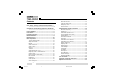
Contents User Safety, Training, and General Information ------------------------------------------------------------------- 4 Compliance with RF Energy Exposure Standards ---------------------------------------------------------------- 4 FCC Compliance --------------------------------------------- 5 Precautions ---------------------------------------------------- 5 Product Inspection ------------------------------------------ 7 Radio Installation --------------------------------------------- 8 Radio Overvie
User Safety, Training, and General Information READ THIS IMPORTANT INFORMATION ON SAFE AND EFFICIENT OPERATION BEFORE USING YOUR HYT MOBILE RADIO. Compliance with RF Energy Exposure Standards Your HYT mobile radio is designed and tested to comply with a number of national and international standards and guidelines (listed below) regarding human exposure to radio frequency electromagnetic energy.
FCC Licensing Requirements FCC Compliance Part 15 Compliance This equipment has been tested and found to comply with the limits for a Class B digital device, pursuant to part 15 of the FCC Rules. These limits are designed to provide reasonable protection against harmful interference in a residential installation. This equipment generates, uses and can radiate radio frequency energy and, if not installed and used in accordance with the instructions, may cause harmful interference to radio communications.
z Do not expose the radio to direct sunlight over a long time, nor place it close to heating source. Safety:It is important that the operator is aware of, and understands, hazards common to the operation of any radio. z Do not place the radio in excessively dusty, humid areas, nor on unstable surfaces. Installation Safety Guidelines z Refer service to qualified technicians only. z Do not mount the mobile radio overhead or on a sidewall unless you take special precautions.
Product Inspection Please carefully unpack the radio. Before use, it is recommended that you inspect the product as follows. First check the shipping carton for any signs of damage. Confirm the supplied product against the packing slip to assure accuracy. If any items are missing or have been damaged during shipment, please file a claim to the carrier immediately.
Radio Installation Installing the Radio 1. Attach the mounting bracket, using the 4.8 x 20mm selftapping screws, in a location where convenient operation is accessible. 2. Connect the antenna and the supplied power cable to the radio. 3. Slide the radio into the mounting bracket and secure it using the Adjustment screws. 4. Mount the microphone hanger, using the 4 x 16mm selftapping screws, in a location where it will be within easy reach of the user. 5.
Radio Installation Installation Tools The following tools are required for proper installation of your radio: z Electric drill: ¡é6mm or above z Cross head Screwdriver ¡ö Warnings: 1. The radio operates in 13.6 ¡À 5£¥V negative ground systems only. Check the voltage and polarity of the power supply on the vehicle before installation. 2. Be sure to check how far the screw will extend below the radio surface to avoid damage to the auto wiring or auto parts when drilling mounting holes. 3.
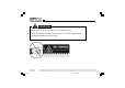
Radio Overview Front Panel View 4. Up/Down Key Volume Up/Down, Channel Up/Down, Zone Up/Down features can be programmed to the keys (set by your dealer). 5. Indicator 6. Speaker 7. Programmable Function Key (PF1-PF6) Your dealer can program these keys as shortcuts to various radio features. Please refer to “Programmable Function Key” section. 1. Power Switch Press to switch the radio on/off. 2.
Radio Overview LCD Display Indicator Description 1. 2. 3. 4. 1. 2. 3. Display zone / channel number. Display zone / channel label (set by your dealer, up to 12 alphanu meric characters). Display channel Frequency Display the preprogrammed functions Display zone / channel number. Display transmit power level (H, M or L). Display the preprogrammed functions A SCAN CALL Appears when the selected channel is busy. Appears when [MONI] key is pressed to disable CTCSS, CDCSS, DTMF or 2-Tone/5-Tone.
Radio Overview Programmable Function Key 18.TXPower PF1-PF6 key can be programmed with the following auxiliary functions: 19.Scan Add/Del 1. Off 2. VOL UP 3. VOL Down 4. CH Up 5. CH Down 6. Zone Up 7. Zone Down 8. MoniA 9. MoniB 10.MoniC 11. MoniD 12.DLabel 13.Dfreq 21.T A 20.Reverse 22.SELSQL 23.HomeCH 24.P A 25.HornAlert 26.LCDBL 27.Scramble 28.Compand 29.AUX A 30.AUX B 31.Send GPS 14.Dmode 32.Emergency 15.UserTone 33.Message 16.Sel2Tone 17.
Radio Overview Rear Panel View 1. Antenna Connector Used to connect external antenna. 2. Power input Connector Adopt HYT-authorized DC power cable and 13.6 V input AC power. 3. Speaker Jack Used to connect external speaker and only available for the plug of 3.5 mm. 4. GPS Antenna Jack 5.
Basic Operations Turn the Radio On/Off Adjust the Volume Press the Power switch to switch the radio on. Selector Knob, [¡ø] / [¨‹] or the function keys PF1-PF6 can Press and hold the Power switch for approximately 1 second to switch the radio off. be programmed with VOL Up / VOL Down features to adjust volume level. If Power on Password is set to protect your radio, “Chk P” and the cursor will appear on the display when power is turned on.
Basic Operations z Monitor Unmute-Momentary Hold down the [MONI] key to open CTCSS/CDCSS/DTMF/ 2-Tone/5-Tone signalling squelch. Release to close the signalling squelch. z Monitor Unmute-Toggle Press the [MONI] key to open CTCSS/CDCSS/DTMF/2Tone/5-Tone signalling squelch. Press again to close the signalling squelch. z Carrier Squelch-Momentary Hold down the [MONI] key to open carrier squelch; Release to close the carrier squelch. z Carrier Squelch-Toggle Press the [MONI] key to open carrier squelch.
Basic Operations Transmit 1. Press the key programmed as [MONI] to make sure that the selected channel is not in use. 2. Hold down the [PTT] key. 3. Dial a DTMF number using the microphone keypad. Step 3 is not necessary all the time. 4. Speak into the microphone with normal voice. The LED glows red during transmission. 5. Release the [PTT] key to receive. 6. When your conversation is finished, return the microphone to its hanger.
Basic Operations Channel Scan (“-SCAN X -” in List zone scan mode, “X” is the current list number). ¡ö ¡öScan Types Note: Scan function can be used only when two or more channels are in the scan list. z Single Zone Scan All channels in the current zone that have been added to the scan list can be scanned. z Multi Zone Scan All channels within all the zones that have been added to the scan list can be scanned.
Basic Operations z Carrier Operated Scan Scanning remains on an active channel until there are no activities; while the channel is free, the radio remains on the channel for the programmed Dropout Delay Time (programmed by your dealer) before it resumes scanning. z Time Operated Scan Scanning remains on the active channel for only the programmed Dropout Delay Time (programmed by your dealer) before it resumes scanning.
Basic Operations ¡ö Look Back Temporary Disable ¡ö Off Hook Scan When scanning looks back and stops on a priority channel, press the key programmed as [Add/Del] to deactivate the Look Back function. ¡ö Nuisance Channel Temporary Delete Normally scanning is not controlled by microphone hook status, it also means that the radio always scans, and stops by signal presence. But if your dealer has programmed Off Hook Scan feature, microphone must be on hook for scanning.
Basic Operations DTMF Call ¡ö Manual Dial Hold down the [PTT] key, then enter the DTMF number by pressing the keys ([0] ~ [9], [*], [#]) on optional microphone keypad. Audible tone sounds when corresponding DTMF tone is transmitted. The radio can be programmed by your dealer to remain in transmit mode for 2 seconds after releasing the [PTT] key. Press any numeric key within 2 seconds to continue transmission.
Basic Operations You can enter the digits 0-9, A-F. To enter A,B,C,D,E,F, hold down the [PTT] key, then enter 2, 5, 8, 0, *, # respectively. 3. Press the [#] key, “— — —” appears on the LCD indicating the memory location. 4. Enter the desired memory location number (01¡«32). 5. Press the [#] key again to store the DTMF number into the memory location. If you enter a wrong digit or decide not to dial the number, press any key other than the power switch on the front panel to exit. 2.
Basic Operations Code Squelch The code squelch feature can be programmed by your dealer. If this feature is activated, squelch turns on only when the received DTMF/2-Tone/5-Tone code matches the radio ID code (set by your dealer). Otherwise, your radio will not respond to the calls. ¡ö Receive 1. When the received DTMF/2-Tone/5-Tone code matches the radio ID code (set by your dealer), squelch turns on and you will hear the call without any further action after an alert tone/Transpond finishes. 2.
Basic Operations 4. Signalling squelch will turn back ON when you press the key programmed as [MONI] or when no signal is received for the preset time period. Auto Transpond The Auto Transpond function can be programmed by your dealer to use with the Code Squelch function. When activated, the radio will send a transpond signal when receiving the matching code.
Basic Operations ¡ö TOT Reset Time Reset time (Off, 1-15 seconds ) is set by your dealer. Stun code (1-16 digits) is programmable. When receiving the stun code, the radio will enter stun mode. The radio will return to normal mode upon receiving a revive code (stun code + [#]). Emergency Call z Inhibit transmission TOT won’t reset even after PTT is released unless the TOT Reset Timer has expired.
Programmable Auxiliary Functions Your dealer can program the following auxiliary functions to the programmable keys PF1-PF6. CTCSS/DCS encoding signals also change to be the same as the decoding signals. Reverse Frequency Press the key programmed as [TA] to toggle the Talkaround function ON and OFF. If communications between radios are disrupted because of a long distance from the repeater, reverse frequency function can be used to re-establish communications to another radio.
Programmable Auxiliary Functions Note: If the squelch level is set too high, you may not efficiently receive weak signals; if the level is set too low, you may hear a constant white noise, a sputtering noise, or unwanted signals. User Selectable Tone (CTCSS/DCS) This function can be programmed by your dealer to temporarily change the preset CTCSS/DCS frequency on a channel. 1. Select your desired channel. 2. Press the key programmed as [UST] to enter the UST mode.
Programmable Auxiliary Functions Dual Home Channels Selectable 2-Tone Encode Press the key programmed as [Home CH], the radio will go to the programmed home channel. 1. Press the key programmed as [TTS], the programmed 2-Tone code or name will be displayed on the LCD. When dual home channels are set, press the key programmed as [Home CH] to switch to Home Channel 1, press again to switch to Home Channel 2, and press for the third time to return to the original channel. 2.
Programmable Auxiliary Functions 4. Release the [PTT] key, signalling squelch turns off and radio LED flashes orange. 5. Press the key programmed as [MONI], signalling squelch turns back on. Note: The radio will opens signalling squelch automatically if no signal is received for the preset period of time. Display Frequency Press the key programmed as [DFreq], LCD will display the frequency of the current channel. Display Label Press the key programmed as [DLabel], LCD will display channel label.
Programmable Auxiliary Functions GPS Report When GPS receiver is installed, press the key programmed as [Send GPS] to transmit your position data. £© Short Message £¨ £¨under development£© £© Status Message£¨ £¨under development£© Optional Signalling (DTMF/2-Tone/5-Tone) The preset functions are activated when the received signal matches the optional signalling.
Programmable Auxiliary Functions ¡ö CTCSS/DCS AND / OR DTMF/2-Tone/5-Tone Signalling Logic AND OR Squelch Unmutes only when both CTCSS/DCS and Optional Signalling (2-Tone/5-Tone/DTMF) are received and matches the preset one on selected channel. Unmutes when either CTCSS/DCS or Optional Signalling (2-Tone/5-Tone/DTMF) is received and matches the preset one on selected channel.
User Set Mode Turn the power on while holding down the [PF1] key, the radio enters User Set mode after correct power-on password is entered (if Power-On Password is set). In User Set mode, the following menus can be selected: z Main Menu No. 1 2 3 4 5 Menu Item Function Set Power On Text Power On Password UST Code Key Assignment LCD Display Function Set Power On Text PWR Password UST Code Key Assign Press the [PF6] key to enter the selected menu.
User Set Mode ¡ö Function Set Select “Function Set” in main menu and press the [PF6] key to make settings as following: Function Set No.
User Set Mode ¡ö Power On Password Select “PWR Password” in the main menu and press the [PF6] key to make settings. “Power On Password” will be displayed. Press the [PF1] key to enter Password Edit mode. Please refer to Appendix 1 “Entering Characters” for more details. Function Setting Blank Number Power On Password Power On Password Display Remarks —————— Please refer to Appendix 1 “Entering Characters”. 88888888 Numeric character only (8 digits maximum).
User Set Mode No. 3 UST Code Display R Off CTCSS R (EIA standard mode) CTCSS 67.0 67.0-254.1Hz R CTCSS 254.1 CTCSS R (step: 0.1Hz) CTCSS 67.0* 67.0-254.1Hz R CTCSS 254.
User Set Mode No. Function 3 RX Signalling UST Code Display R CDCSS 023¢ñ R CDCSS 754¢ñ CDCSS R (1 step mode) CDCSS 000¢ñ* 000-777 Reverse R CDCSS 777¢ñ* Setting CDCSS (standard mode) 023-754 Reverse OFF T Remarks [PF5]: OFF/CTCSS/CDCSS Off 4 CTCSS (EIA standard mode) 67.0-254.1Hz TX Signalling CTCSS (step: 0.1Hz) 67.0-254.1Hz T CTCSS 67.0 R CTCSS 254.1 T CTCSS 67.0* T CTCSS 254.
User Set Mode UST Code No.
User Set Mode ¡ö Key Assignment Select “Key Assign” in the main menu and press the [PF6] key to program the programmable keys PF1-PF6 as following: No.
User Set Mode No.
User Set Mode No.
User Set Mode No.
User Set Mode No.
User Set Mode No.
User Set Mode No.
User Set Mode No.
User Set Mode No.
User Set Mode No.
User Set Mode No.
User Set Mode Key Assignment No.
User Set Mode No.
Appendix 1 Entering Characters Entering characters with an optional microphone keypad KEY 1 1 Space 2 A 3 D 4 G 5 J 6 M 7 P 8 T 9 W 0 A @ B + C ( D , * # PTT CHARACTER NUMBER Number of times key is pressed 2 3 4 5 6 B E H K N Q U X c f i l o q v x C F I L O R V Y a d g j m S t Z b e h k n p u w 7 8 r s y z ! # $ % ^ & * / = \ _ ) < > [ ] { .
Appendix 1 Entering Characters Entering characters without a keypad Optional Accessories 1. Turn Selector Knob to choose the character to be entered. 2. Press the [PF2] key to toggle among number, uppercase letter, lowercase letter and symbol. 3. Press the [PF3] / [PF4] key to move the cursor forward/ backward. 4. Press the [PF1] key to clear the input. 5. Press the [PF6] key to confirm the input.
HYT endeavors to achieve the accuracy and completeness of this manual, but cannot guarantee its accuracy at all time. All the above specifications and design are subject to change by HYT without notice. All the reproduction and translation of this manual without authorization of HYT is not allowed.