
User Guide

Receiver Adjustment
Measurement Adjustment
Item Condition
Test Instrument Terminal Part Method
Specifications/
Remarks
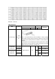
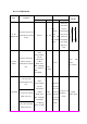
15. RF
bandpass filter
Enter item “B”; Each CH
corresponds to a specific
TX freq.
Scanner ANT . TP1
First
manually
adjust
TC101, then
the software
setting
Set the gain
value to the
max; the
corresponding
freq is on the
rightmost of
the bandpass
wave. Press
[P2] key to
save.
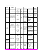
16. Max.
SINAD
Frequency: RX Center;
adjust to CH1(C);
corresponds to a specific
freq.
Radio
Communication
Test Set
SSG Output:
-47dBm
MOD: 1KHz
DEV: ±3KHz(W)
±1.5KHz(N)
Filter:
0.3-3.0KHz
ANT
SP Jack
K301
Check Max.
volume:
4.6V or above
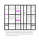
1. CH: RX Center,
manually adjust to CH
1(C).
2. CH: RX LO, manually
adjust to CH 2 (L).
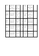
17. Sensitivity
3. CH: RX HI, manually
adjust to CH3 (H).
Radio
Communication
Test Set
SSG Output:
-116dBm
MOD: 1KHz
DEV: ±3KHz(W)
±2.4KHz(M)
±1.5KHz(N)
Filter:0.3-3.0KHz
ANT
SP Jack
Wide/narro
w
band switch
(turn on the
power while
holding [P1]
key to enter
CH setting
mode)
[P2] key for CH
adjustment
Check
SINAD:
12dB or above