THANK YOU! Thank you for your purchase of HYT TM-610 Mobile Radio. This easy-to-use radio will deliver you instant and reliable communications at peak efficiency. Please read this manual carefully before use. The information presented herein will help you to derive maximum performance from your radio.
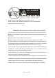
H OT S U RFACE Avoid c onta ct durin g prolonged us e Do not touch the metal surface of the radio while it is in use. Do not mount the radio such that the chassis can come in contact with skin. High temperatures may burn you skin. MANDATORY SAFETY INSTRUCTIONS TO INSTALLERS AND USERS ════════════════════════════════════════════════════════════════ z Use Only manufacturer or dealer supplied antennas and power cable (32V/15A, with safety fuse).
Contents Caution MANDATORY SAFETY INSTRUCTIONS Safety and General Information Product Safety and RF Exposure Compliance FCC Licensing Information Operation Guidelines Installation Guidelines Product Inspection Installation Radio Overview Basic Operations Turn Radio On/Off Adjust the Volume Monitor Select a Channel Select a Zone Receive a Call Send a Call Select Power Level BOT ID and EOT ID Scan Busy Channel Lockout (BCL) BCL Override DTMF Call Code Squelch Off Hook Decode Time-out Timer (TOT) Emergency Cal
User Selectable CTCSS/CDCSS (UST) Public Address (PA) Home Channel 2-Tone Encode Select Display Frequency Display Mode Voice Compander Scrambler Key Assignment Optional Accessories 第 页 共 32 页 4
Safety and General Information The following general safety precautions as would normally apply, should be observed during all phases of operation, service and repair of this equipment. * Do not attempt to configure the radio while driving; it is too dangerous. * Do not operate your radio when someone is either touching the antenna or standing within 2 or 3 feet of it, to avoid the possibility of radio frequency burns or related physical injury.
Product Safety and RF Exposure Compliance Your HYT mobile radio is designed and tested to comply with a number of national and international standards and guidelines (listed below) regarding human exposure to radio frequency electromagnetic energy. This radio complies with the IEEE and ICNIRP exposure limits for occupational/controlled RF exposure environment at operating duty factors of up to 50% transmitting and is authorized by the FCC for occupational use only.
FCC Licensing Information Part 15 Compliance This equipment has been tested and found to comply with the limits for a Class B digital device, pursuant to part 15 of the FCC Rules. These limits are designed to provide reasonable protection against harmful interference in a residential installation. This equipment generates, uses and can radiate radio frequency energy and, if not installed and used in accordance with the instructions, may cause harmful interference to radio communications.
Operation Guidelines * For vehicles equipped with electronic anti-skid braking systems, electronic ignition systems or electronic fuel injection systems, interferences may occur during the radio transmission. If the foregoing electronic equipments are installed on your vehicle, please contact your dealer for further assistance to make sure that the radio transmission will not interfere with these equipments.
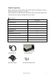
Product Inspection Before unpacking the TM-610 mobile radio, please inspect the packaging for signs of damage and report any damage to your dealer. Upon unpacking of the TM-610 mobile radio, please ensure that all items shipped were received, report any missing or damaged items to your dealer. ▇ Accessories Item Qty.
Adjust knob Fuse Bracket Mounting Screw Set DC Power Cable 第 页 共 32 页 10
Installation ▇ Install the radio 1. Attach the bracket, with 4.8 x 20 mm self-tapping screws, in a location where convenient operation is accessible. 2. Connect the supplied antenna and power cable to the radio. 3. Slide the radio into the bracket, and secure it with the Adjust knobs. 4. Attach the microphone hanger, with 4 x16 mm self-tapping screws, in a location where the user is easy to reach. 5.
8. 9. 10. 11. 12. Antenna pedestal 4 × 16 mm self-tapping screw Microphone hanger Mounting bracket 4.8 × 20 mm self-tapping screw ▇ Installation Tools 1. Electric drill: ¢6mm or above 2. Cross head screwdriver 3. Hex socket sleeve (used for mounting 4.8 × 20 mm self-tapping screw) ▇ Warning * The radio operates with a power supply of 13.6 ± 15%V negative grounding only. Please check polarity and voltage prior to installing the radio.
Radio Overview ▇ Front Panel ① Volume Control Knob Turn the Volume Control Knob clockwise to increase the volume, or counter-clockwise to decrease the volume. ② LCD Please refer to the “LCD Display” section for details. ③ Programmable Functions Keys ([▲] / [▼]) The [▲] / [▼] keys are programmable with auxiliary functions by your dealer. Please refer to the “Programmable Functions Keys” section.
▇ Rear Panel ① 15PIN (external expansion) ② External Speaker Jack Plug the external speaker connector (¢3.5mm) into this jack. ③ Power Inlet Use the DC power cable supplied by HYT to inlet 13.6V DC power supply. ④ Antenna Pedestal To connect the external antenna.
▇ Programmable Function Keys The [P1]-[P4], [▲]/ [▼] keys are programmable with auxiliary functions as follows: 1. Off 2. CH Up 3. CH Down 4. Zone Up 5. Zone Down 6. Monitor A 7. Monitor B 8. Monitor C 9. Monitor D 10. Display Frequency 11. Display Mode 12. User Selectable CTCSS/CDCSS (UST) 13. 2-Tone Encode Select 14. TX Power Select 15. Scan 16. Scan Add/Delete 17. Reverse Frequency 18. Talk Around 19. Select Squelch Level 20. Home Channel 21. Public Address 22. Scrambler 23. Voice Compander 24.
▇ LCD Display Figure 1 LCD panel Indicator Description Displays CH number/name, zone number/name, DTMF number, frequency, menu and options, etc. Lo Low power output. Press the [Monitor] key: 1. The “ ” icon is displayed when CTCSS/CDCSS, 2-Tone decoding is off. 2. The “ ” icon is displayed when speaker is unmuted. Appears when activity is detected on non-priority channel during the Scan status. Appears when transmitting a selective call.
Basic Operations Turn Radio On/Off Press the power switch to turn on the radio. Press and hold down the power switch for about 1 second to turn off the radio. Adjust the Volume Turn the Volume Control Knob clockwise to increase the volume, or counter-clockwise to decrease the volume. During adjusting, please note that if the radio is programmed with CTCSS/CDCSS or 2-Tone signalling squelch, noise will not be heard from local speaker even though you turn the volume control knob fully clockwise.
The RX/TX frequency on each channel is set by your dealer. Press the [CH Up] key (programmable) to select a higher numbered channel; press the [CH Down] key (programmable) to select a lower numbered channel. Select a Zone The [▲]/[▼], [P1]-[P4] function keys are programmable by your dealer to select a zone. The RX/TX frequency on each channel is set by your dealer. Press the programmed [Zone Up] key to select a higher numbered zone; press the programmed [Zone Down] key to select a lower numbered zone.
prompts an error tone, and the power level will not change. * If you switch to low power on a channel that was set with high power, this configuration is done on all other channels that were set with high power. BOT ID and EOT ID Your dealer may configure whether to transmit Connect ID (BOT ID) and Disconnect ID (EOT ID), when connecting or disconnecting a repeater or telephone system. The following modes are programmable: 1. BOT ID occurs on each press of [PTT]. EOT ID occurs on each release of [PTT]. 2.
exits the scan mode. 2. Activate the Monitor function. 3. Receives carrier that satisfy radio unmute condition ▇ Scan Resume If scanning pauses on an active channel, the scanning will resume according to the scan resume mode. The scan resume mode is programmable by your dealer for Carrier operated scan or Time operated scan. 1.
programmed Scan Add/Delete key. Note: Only channels that added into the scan list can be scanned. ▇ Nuisance Channel Delete Temporarily deletes a specific channel from your scan list during the scan sequence. When scan pauses on an unwanted channel such as a noise channel, press the programmed Add/Del Scan key to temporarily deleted the channel from the scan list, then scanning reinitiates immediately. Note: the temporary delete is not memorized once radio exits from the scan mode.
DTMF Call ▇ Manual Dial Press any key from the DTMF keypad of the microphone, while holding down the [[PTT]], to transmit the DTMF frequency, and the DTMF tone will be heard from the local speaker. Release the [[PTT]] to remain transmission for 2s (programmable by your dealer), press a numeric key within the 2s to continue transmission. ▇ Keypad Auto [PTT] If the feature is enabled by your dealer, press numeric key to transmit DTMF frequency without pressing the [[PTT]].
1. Press the [#] key on the microphone keypad, then the LCD displays “D ------”. 2. Enter the desired number (range from 0~9, A~F) via the microphone keypad. If you want to enter A, B, C, D, E, F, please enter 2, 5, 8, 0, *, # respectively while holding down the [PTT]. 3. Press the [#] key, the “ - - ” is displayed following the “D” character, indicating the location of the memory number. 4. Enter the desired memory number (01~32). 5.
2. Press the [0] key twice, then the last dialed number (up to 16 digits) is dialed and displayed on LCD. 3. Press the [PTT], the number is transmitted. Note: The redial memory is cleared once radio power off. Code Squelch This feature can be enabled/disabled by your dealer. If the feature is enabled, the preset 2-Tone controls radio mute/unmute. The radio will not unmute until matched signalling is received. ▇ Receive 1.
Off Hook Decode If the feature is enabled by your dealer, CTCSS/CDCSS signalling is active no matter the microphone is in the off/on hook condition. If the feature is disabled, CTCSS/CDCSS signalling is disabled while the microphone is in the off hook condition. Time-out Timer (TOT) ▇ Time-out Timer(TOT) The feature allows for more efficient use of channels by limiting the amount of time of each transmission. It protects the radio from damage caused by long time transmission.
will enter the Emergency Call mode and switch to the preset Emergency Zone/Channel. The radio will firstly transmit within the preset time period, and then receive within the preset time period, and so does the cycle. The radio will back to the channel before the Emergency Call mode, upon re-holding down the Emergency Call key (programmable as long or short press).
Selectable Squelch Level (SQL) 1. Upon press the programmed SQL key, LCD displays the current squelch level as the following figure: 2. Select the desired squelch level via the programmable function key [▲]/ [▼]. 3. Pressing any key from [P1]-[P4] to save the selected squelch level. The LCD resumes its initial display. Note: High squelch level may cause the radio to ignore weak signals; while low squelch level may cause noise or unwanted signals to be heard.
3. Speak into the microphone while holding down the [PTT], the PA process initiates, and the LCD displays “PA ON”. While in PA mode or the PA process initiates, you can adjust the volume via the volume control knob. 4. Release the [PTT] to end PA process, then the radio returns to the PA mode, and the LCD displays “PA”. Note: While using the PA system, the optional PA accessories and external speaker must be installed by your dealer.
1. Channel alias. 2. Zone number followed by channel number, “1 –CH 1”. 3. Zone alias. 4. Channel frequency. 5. Channel number followed by zone number, “CH 1– 1”. Voice Compander Press the programmed Voice Compander key to toggle the voice compander feature ON or OFF. When the feature enabled, LCD displays the “ ” icon. Scrambler Press the programmed Scrambler key to toggle the Scrambler feature ON or OFF. When the feature enabled, the LCD displays the “ ” icon.
Key Assignment ▇ Programmable Function Keys [P1]-[P4], [▲]/ [▼] are programmable Function keys. Key Assignment No.
18 Talk Around Talk Around 19 SQL Selectable squelch level 20 Home Channel Home Channel 21 Public Address Public Address 22 Scrambler Scrambler 23 Voice Compander Voice Compander 24 Emergency Call Emergency Call ▇ Hook/Monitor “Hook/Monitor” function can be set respectively via the programming software. No. Function 1 Hook/Monitor Setting Hook Detect Monitor Remarks Select when using palm microphone. Select when using desktop microphone.
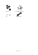
Optional Accessories Antenna Keypad Microphone (SM07R1) Programming Cable (PC06) Palm Microphone (SM07R2) Cloning Cable (CP06) HYT endeavors to achieve the accuracy and completeness of this manual, but no warranty of accuracy or reliability is given. All the above specifications and design are subject to change without notice due to continuous development. No duplication or distribution of this manual or any portion thereof shall take place without the express written permission of HYT.