
User's Manual

22
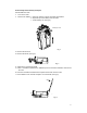
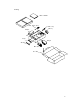
6. Remove the main PCB: a. Remove the two screw caps on top of the unit.
b. Remove the five screws between PCB and the chassis.
c. Loosen the weld between antenna pedestal and PCB
using a soldering iron.
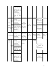
d. Lift the PCB off. (See fig.4)
Fig.4
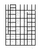
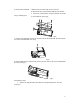
7. Remove the small PCB: Loosen the screw to remove the small PCB. And then loosen
the socket of flexible PCB. (See fig.5)
Fig.5
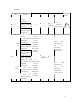
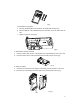
8. Disassemble PTT key: Push the tab on PTT out of the hole on the case to disassemble
PTT key. (See fig.6)
Fig.6
Assemble the radio
1. Attach PTT: Align the tab on PTT with the corresponding hole on the case.
(See fig.7)