
User's Manual

10
wideband or narrowband. W/N pin of IC500 outputs wideband (high level) and
narrowband (low level) signal.
5) AF Amplifier
The result AF signal from IC204 is amplified by IC606, and then passes through AF
processing chip IC601 and compander IC603. The processed AF signal is then
amplified by an AF power amplifier (IC720) to drive the speaker.
4. Transmitter
1) AF and Signaling
Modulating signal from the microphone passes through Q700 switch and compander
IC603 before it enters AF processing chip IC601. Under the control of MCU, IC601
produces DTMF/CTCSS/CDCSS/2-Tone/5-Tone signaling, which then pass through
MOD and enter VCO together with the modulating signal for direct FM modulation.
(See fig.5)
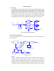
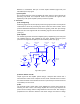
2) RF Amplifier
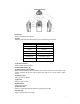
The transmit signal from VCO buffer amplifier (Q310) is amplified by Q101 and Q102.
The amplified signal is then amplified by the power amplifier Q105 and Q107
(include a two-stage FET amplifier) to create 4.0W RF power. (See fig.4)
D
C
B
A
Title
AMP
Q101.102
5T
DRIVE AMP
Q105
FINAL AMP
Q107
ANT SW
D101 LPF
ANT
ANT SW
D201.202
RX
Q106
SW
Q109
SW
5T
IC100
APC
DET
Q103.Q104
B SW
B
APC
5T
TH101
SW
Q110
5T
Q108
SW
5TC
Fig.4 APC System
3) Antenna Switch and LPF
Output signal from RF amplifier passes through a low-pass filter network and a
transmit/receive switch circuit comprised of D101, D201 and D202 before it reaches
the antenna terminal. D201 and D202 is turned on (conductive) in transmit mode and
off (isolated) in receive mode.
4) APC
The automatic power control (APC) circuit stabilizes the transmit output power by
detecting the drain current of final stage amplifier FET. IC100 (2/2) compares the
preset reference voltage with the voltage obtained from final current. APC voltage is
proportional to the difference between auto detect voltage and reference voltage