
User's Manual


Description of TC-700 Desktop Charger
59
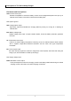
Figure Ⅳ Battery Voltage Divider
For Li-Ion battery packs, the resistor values R
B1
and R
B2
are calculated by the following equation:
Where N is the number of cells in series. The end-to-end input impedance of this resistive divider
network should be at least 200KΩ and no more than 1MΩ.
A NiCd or NiMH battery pack consisting of N series-cells may benefit by the selection of the R
B1
value to be N-1 times larger than the R
B2
value.
In a mixed-chemistry design, a common voltage divider is used as long as the maximum charge
voltage of the nickel-based pack is below that of the Li-Ion pack. Otherwise, different scaling is
required.
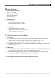
4. Charge Current Control
The bq2000T controls the charge current through the MOD output pin. The current-control circuit
supports a switching-current regulator with frequencies up to 500kHz. The bq2000T monitors charge
current at the SNS input by the voltage drop across a sense-resistor, R
SNS
, in series with the battery
pack. See Figure Ⅴ for a typical current-sensing circuit. R
SNS
is sized to provide the desired
fast-charge current (I
MAX
).
If the voltage at the SNS is lower than VSNSLO or higher than VSNSHI, the bq2000T switches the
MOD output high to pass charge current to the battery. When the SNS voltage is less than VSNSL or
greater than VSNSHI, the bq2000T switches the MOD output low to shut off charging current to the
battery.
Figure Ⅴ Current-Sensing Circuit