
User's Manual

TC-700 Adjustment Description
19
Adjustment Description
Adjust the radio by PC programming software or by manual adjustment. In manual adjustment mode, the
adjustment method is shown as follows: (Refer to “Software Specification” for the manual adjustment
mode)
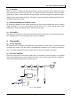
Required Test Instrument
Radio Communication Test Set 1 set
Scanner 1 set
3A/10V Power Supply 1 set
Digital Voltmeter 1 set
3A Ammeter 1 set
Adjustment
1. Adjustment in user mode
Firstly ground the SELF point, turn on the power by holding down TK for 2 seconds, and then the radio
enters reset mode with green LED flashing twice. Turn the channel selector knob to the selected channel
and press PTT, the radio data is all reset (All clone modes will be automatically activated when reset is
completed). Refer to All Reset Mode in Software Specification for more details:
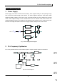
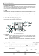
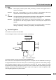
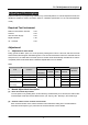
VCO
Measurement Adjustment
Item Condition
Test
Instrument
Terminal Parts Method
Specification
/Remarks
1. Setting Power supply voltage
1. CH: TX high 3.9V±0.1V 2.Transmit VCO
lock voltage
2. TX Low Check >0.5V
1. CH: RX high 3.9V±0.1V 3.Receive VCO
lock voltage
2. RX low
Digital
Voltmeter
CV TC301
TC302
Check >0.5V
2. Manual Adjust Mode Description
(1) Enter the manual adjust mode
Turn the power on by holding down TK and SK2 key simultaneously for 2 seconds, the radio enters
manual adjust mode with red LED flashes twice. (TK: Top key; SK1: Side key1; SK2: Side key2)
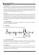
(2) Channel number on the channel selector knob
Each channel number on the channel selector knob is defined a setting item. The bandwidth is
25 KHz and low frequency (F1) each time the channel selector knob is rotated.