
User's Manual

TC-700 Circuit Description
13
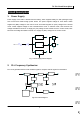
3) Antenna Switch and LPF
Output signal from RF amplifier passes through a low-pass filter network and a transmit/receive switch
circuit comprised of D102,D103 and D104 before it reaches the antenna terminal. D103 and D104 is
turned on (conductive) in transmit mode and off (isolated) in receive mode.
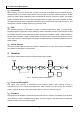
4) APC
The automatic power control (APC) circuit stabilizes the transmit output power by detecting the drain
current of final stage amplifier FET. IC101 (2/2) compares the preset reference voltage with the voltage
obtained from final current. APC voltage is proportional to the difference between auto detect voltage
and reference voltage output from IC101 (1/2). The output voltage controls FET power.
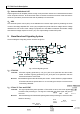
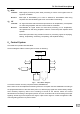
5. Base Band and Signaling System
The block diagram of signaling section is shown as figure 5.
Fig. 5 AF and Signaling Circuit
1) CTC/CDC
Transmit: CTC/CDC signaling produced by CTC_PLL pass a low pass filter and then enters
VCXO. CTC/CDC signaling produced by CTC_OUT pass a low pass filter and then
mixed with AF before enters VCO.
Receive: Demodulated signal enters MCU after pass IC404、IC405. MCU then judges whether
CTC/CDC matches the preset values or not. According the result, the out tone will be
controlled by AFMUTE.
2) 2-Tone / 5-Tone and DTMF
Transmit: The signal produced by MCU provides a TX and SP out tone, and is then applied to
the base band processing IC. The signal in mixed with the audio signal and goes to
the VCO。
Receive: Demodulated signal is filtered after passing base band processing IC, and then enters
MCU for decoding.