
User's Manual


TC-700 Circuit Description
12
3) IF Amplifier
The first IF signal is amplified by Q206 before passing through crystal filter and by Q204 after crystal
filter and then enters IF processing chip IC204. The signal from IC204 is mixed with the second oscillator
signal again in IC204 to create a 450 KHz second IF signal. The second IF signal then passes through a
450KHz ceramic filter (wideband: CF201,narrowband: CF202) to eliminate unwanted signals before it is
amplified and detected in IC204.
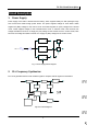
4) Narrowband/Wideband Switch Circuit
Pin WCON and NCON of IC500 outputs wideband (high level) and narrowband (low level) controlling
signal respectively to turn on corresponding diode-connector, and to choose ceramic filter CF201
(wideband) or CF202 (narrowband) to filter useless spurious signal.
5) AF Amplifier
The resulting AF signal from IC204 enters base band processing chip IC408. The processed AF signal is
then amplified by an AF power amplifier (IC401) to drive the speaker.
4. Transmitter
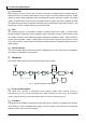
1) AF and Signaling
AF signal from the microphone is amplified and low-pass-filtered in IC402 before it enters base band
processing chip IC408, which also enters CTC/CDC/DTMF/2-Tone/5-Tone etc signaling generated by
CPU. The IC408 processed mixing signal enters VCO for direct FM modulation (see fig.5).
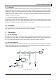
2) RF Power Amplifier
The transmit signal from VCO buffer amplifier (Q111) is amplified by Q101 and Q102. The amplified
signal is then amplified by the power amplifier Q103 and Q104 (including a two-stage FET amplifier) to
create 4.0W (UHF)/5.0W (VHF) RF power (see Fig. 6).
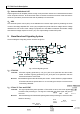
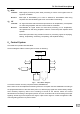
Fig. 4 APC System