
User's Manual


TC-700 Circuit Description
10
Circuit Description
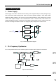
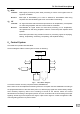
1. Power Supply
Power supply of the radio is derived from the battery, which supplies battery B+ after passing through
fuse 3A and then feeds through power switch. The power supplies voltage for three AVRs. IC504
supplies 5V (M5V) voltage for the control circuit. And IC503 supplies 5V (C5V) voltage for the shared
circuit. IC502 supplies voltage for the transmit/receive circuit. In transmit mode, T5C becomes low
voltage and Q502 is turned on to supply 5V (T5v) voltage for the transmit circuit. In receive mode, R5C
becomes low voltage and Q504 is turned on to supply 5V (R5V) voltage for the receive circuit.
Fig. 1 Power Supply Block Diagram
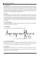
2. PLL Frequency Synthesizer
PLL circuit generates the first local oscillator signal for reception and RF signal for transmission.
Fig.2 PLL Block Diagram