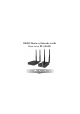
HDMI Wireless Extender with One-way IR (100M) VER 1 1.
Thank you for purchasing this product For optimum performance and safety, please read these instructions carefully before connecting, operating or adjusting this product. Please keep this manual for future reference. Surge protection device recommended This product contains sensitive electrical components that may be damaged by electrical spikes, surges, electric shock, lighting strikes, etc. Use of surge protection systems is highly recommended in order to protect and extend the life of your equipment.
1. Introduction This product is based on H.265 standard solution for transmitting one HD source signal to one HD display. It extends distance up to 330ft/100 meters (In an open environment without Wi-Fi interference) between the encoder and decoder via wireless transmission. It supports one-way IR control. It offers high quality configurable and low-bandwidth H.265 compression video. Input video resolution is up to 1920×1080@60Hz; Output video resolution is up to 1080P@60Hz.
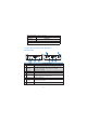
. Specifications Technical HDMI Compliance HDMI 1.3 HDCP Compliance HDCP 1.4 Video Bandwidth 6.75Gbps Input: Up to 1920×1080@60Hz Video Resolution Output: Up to 1080P@60Hz Color Space Color Depth RGB, YCbCr 4:4:4 / 4:2:2 8/10/12-bit 6@ .` Input: LPCM 2.0CH 32KHz/44.1KHz/48KHz/ HDMI Audio Formats 88.2KHz/96KHz/176.4KHz/192KHz Output: LPCM 2.
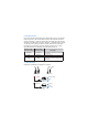
Storage Temperature -4 - 140°F / -20 - 60°C Relative Humidity 20 - 90% RH (no condensation) Resolution / Cable Length 1080P60Hz Feet / Meters HDMI IN / OUT 42ft / 15M The use of “Premium High Speed HDMI” cable is highly recommended. 5. Operation Controls and Functions 5.1 Encoder Panel 8 LINK 1 2 No. Name 8 HDMI IN DC 5V PAIR SERVICE IR OUT 3 4 5 6 7 Function Description 1 Power LED The LED will illuminate red when the encoder is powered on.
5.2 Decoder Panel 8 8 LINK HDMI OUT DC 5V PAIR SERVICE IR IN 3 4 5 6 7 1 2 No. Name Function Description 1 Power LED The LED will illuminate red when the decoder is powered on. 2 LINK LED (Green) The LINK LED flashing means that the encoder and decoder are transmitting video signals. (Please refer to “5.3 Pairing Instruction” for details) 3 HDMI OUT HDMI output port for connecting the HDMI display device. 4 DC 5V Connect the DC 5V/1A power adapter.
5.3 Pairing Instruction Connect the encoder and decoder with an HDMI cable. Power on the decoder firstly, then power on the encoder after the power LED and LINK LED of the decoder are always on. After successful pairing, the LINK LED of the decoder will flash. If the LINK LED of encoder is always on, it indicates that the encoder and decoder has not been connected or paired.
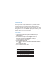
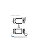
Connection diagram of using IR cables. Encoder DC 5V DVD SERVICE HDMI IN PAIR LINK IR OUT ce is distan ission ansm The tr DC 5V 100M Decoder IR IN LINK SERVICE HDMI OUT PAIR TV DVD remote Note that when the angle between the IR receiver and the remote control is ± 45 °, the transmission distance is 0-5 meters; when the angle between the IR receiver and the remote control is ± 90 °, the transmission distance is 0-8 meters.
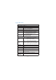
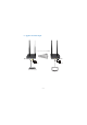
6. Application Example The transmission distance extends up to 100M.
20C