
User's Manual
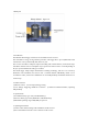

3) Press the test button in the transmitter, if the transmitter’s and receiver’s signal LEDs light
simultaneously, that means they’re working.
4) Plug the flash into the receiver’s hot shoe socket, and fix it; plug the transmitter into the
camera’s hot shoe socket, then transmit signals to control the receiver to trigger flash by pressing
camera’s shutter release.
5) The transmitter will take the 3.5mm PC cord to connect the PC socket of camera. You can use
the same 3.5mm PC (with 6mm converter) Sync cord to connect the receiver and studio light to
trigger the studio light.
6. Setting of Channel Match
The channel selectors are located at the bottom of transmitter and the top of the receiver, and they
must be set up at the same settings before operating.
7. Precautions
1) Use batteries specified in this user guide, and to replace a new battery if the receiver’s signal
LED becoming dim.
2) Prevent the unit from falling and crushing.
3) Keep the unit dry, and avoid electric shock, rain and dampness.
FCC ID: XBYPT0402
This device complies with Part 15 of the FCC Rules.
Operation is subject to the following two conditions:
(1) This device may not cause harmful interference, and
(2) This device must accept any interference received,
including interference that may cause undesired operation.
NOTE: THE MANUFACTURER IS NOT RESPONSIBLE FOR ANY RADIO OR TV
INTERFERENCE CAUSED BY UNAUTHORIZED MODIFICATIONS TO THIS
EQUIPMENT. SUCH MODIFICATIONS COULD VOID THE USER’S AUTHORITY
TO OPERATE THE EQUIPMENT.
Contact Tel : (86) 0755-61116103
Contact Fax : (86) 0755-61116101
E-Mail: cybzc@163.com