
User's Manual
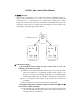
Pin 3 to grounding alternately. At the same time, Pin 4 of MOTOR
socket will export 13.8V voltage and pin 1 will connect to grounding.
When pin 5 of ‘GATE SENSOR’ socket inputs high level(>5V), Pin 4
of ‘MOTOR’ socket will disconnect with interior voltage. Otherwise
when control unit 1# keeps in open status(i.e. control unit 1# of pin 2
of GATE SENSOR socket keeps in low level), it will be closed first
and then execute the above actions.
e). Press ‘ALARM’ key of the handheld transceiver, both control unit 1#
and 2# of Pin 1 of ‘SIGNAL’ socket will export 13.8V voltage and pin
2 connect to grounding, at the same time pin 1 of SIREN will connect
to 13.8V voltage as well.
f) . Press the ‘RESET’ key of the handheld transceiver, both control unit 1#
and 2# of Pin 1 of ‘SIGNAL’ socket will export 13.8V voltage, Pin 2
will connect to grounding, pin 3 will disconnect with interior circuits
and Pin 1 of SIREN socket will be hung.
4. To Set the address code of control unit:
There are two groups of DIP switches (S8, S9) on the PCB of control
unit. 32768 address codes can be set by setting DIP switches.
5. To read the parameters of control unit:
The parameters such as address codes, channel number or work frequency can be
read with the configured software by connecting SET
socket and PC serial
interface.
Ⅲ. Technical Specifications
Frequency range: 453.325~468.000MHz
Modulation mode: FM
Channels: 16
Antenna impedance: 50Ώ
Receiving sensitivity: ≤0.25uV(12dBSINAD)
1st IF: 21.4MHz
2
nd
IF: 455KHz
Audio distortion: ≤3%
Adjacent channel selectivity: ≥65dB
Adjacent channel power: ≥65dB
Output Power: ≤4W
Frequency Stability: ±5ppm
Channel Spacing: 25KHz
Frequency deviation: ≤5KHz
Spurious rejections: ≥70dB
Relative humidity: 95% RH non-condensing
Ambient
temperature: -20~55℃
DC Voltage range: 10.8V~13.8V
Maximum current: ≤9A
Stand-by current: ≤300mA