
User's Manual
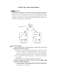
b) When the relays control pin 2 of ‘SIGNAL’ to connect grounding, if
pin 1 of HOSE SENSOR connects to grounding, Pin 1 of SIREN
socket will export 13.8V and Pin 2 will connect to grounding.
c) Press ‘1’ key of the handheld transceiver, the relays of control unit 1#
will control pin 3 of ‘SIGNAL’ socket to disconnect or connect to
grounding alternately, at the same time Pin 4 of ‘MOTOR’ socket will
export 13.8V voltage and pin 1 will connect to grounding. When Pin 5
of ‘GATE SENSOR’ socket inputs high level (>5V), Pin 4 of
‘MOTOR’ socket will disconnect with the interior voltage.
d) Press ‘2’ key of the handheld transceiver, Control unit 2# will execute
the same actions as 1#.
e) Press ‘ALARM’ key of the handheld transceiver, the relays will control
pin 2 of SIGNAL to connect to grounding and pin 1 of SIREN to
13.8V voltage as well.
f) Press the ‘RESET’ key of the handheld transceiver, Pin 1 of ‘SIGNAL’
socket will export 13.8V voltage, Pin 2 will connect to grounding, pin
3 will disconnect with interior circuits. Pin 1 of SIREN socket will be
hung.
3. Working in Dual mode. (‘MODE’ Switch of Control unit 1# and 2#
both turns to ‘DUAL’ position):
a). The indicator Led of ‘Dual Mode’ will turn on. If both control unit 1#
and 2# can communicate well with each other and each one can work
in good condition, the indicator LEDs of both ‘FLAG1’ and ‘FLAG2’
will turn on, otherwise they will flash to indicate there is malfunction.
b). When the relays control pin 2 of ‘SIGNAL’ to connect to grounding, if
pin 1 of ‘HOSE SENSOR’ socket connects to grounding, Pin 1 of
SIREN socket will export 13.8V and Pin 2 will connect to grounding.
c) .While press ‘1’ key of the handheld transceiver, Control unit 1#will
communicate with 2# via wireless radio. If control unit 2# keeps in
closed status(i.e. control unit 2# of pin 2 of GATE SENSOR socket
inputs high level(>5V)), The relays of control unit 1# control pin 1 of
‘SIGNAL’ socket to export 13.8V voltage and to disconnect or connect
pin 3 to grounding alternately. At the same time, Pin 4 of MOTOR
socket will export 13.8V voltage and pin 1 will connect to grounding.
When pin 5 of ‘GATE SENSOR’ socket inputs high level(>5V), Pin 4
of ‘MOTOR’ socket will disconnect with interior voltage. Otherwise
when control unit 2# keeps in open status(i.e. control unit 2# of pin 2
of GATE SENSOR socket keeps in low level), it will be closed first
and then execute the above actions.
d). While press ‘2’ key of the handheld transceiver, Control unit 2#will
communicate with 1# via wireless radio. If control unit 1# keeps in
closed status(i.e. control unit 1# of pin 2 of GATE SENSOR socket
inputs high level(>5V)), The relays of control unit 2# control pin 1 of
‘SIGNAL’ socket to export 13.8V voltage and to disconnect or connect