
User's Manual

Shenzhen Friendcom Technology Development Co., Ltd.
23
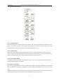
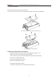
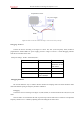
Figure T2: User activate the modem launching 01 code or PN9 code by TRS pin.
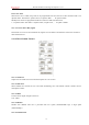
Debugging method-1
Connect the devices according to the figure T1 shows. The VFF (Voice Frequency Filter) should be
programmed as 20Hz-15KHz. DC power supply provide a voltage of 12V/2A. A serial debugging software
sends the AT command to the radio.
Serial port settings:4FSK:9600/19200, 8N1。
AT command
FC-302-4FSK
Remark
AT+TEST=CODE01/r
send code 01
Used for deviation
adjustment of the
4FSK modem
AT+TEST=EXIT/r
Quit from the test
AT+WORKMODE=?/r
Data rate query
AT+WORKMODE=M9600/r
Program the data
rate as 9600bps
Debugging method-2
The second method is easy to conduct. But the channel and coupling mode. The radio should be under
wide band channel spacing for frequency deviation calibration.
Debugging:
Connect the devices according to the figure T2, SW (Switch) is connected between the STS (Pin 12) and
GND.
Close the SW in 30 seconds after the radio is powered up. Then the radio starts to transmit. User adjust the
frequency deviation to 3.3-3.5KHz by adjusting VR2 and reading the deviation value
Comprehensive tester
DC power supply
Radio