
Data Sheet


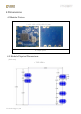
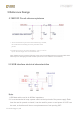
Table Of Contents
FTY Technology Co.,Ltd
5 Reference Design
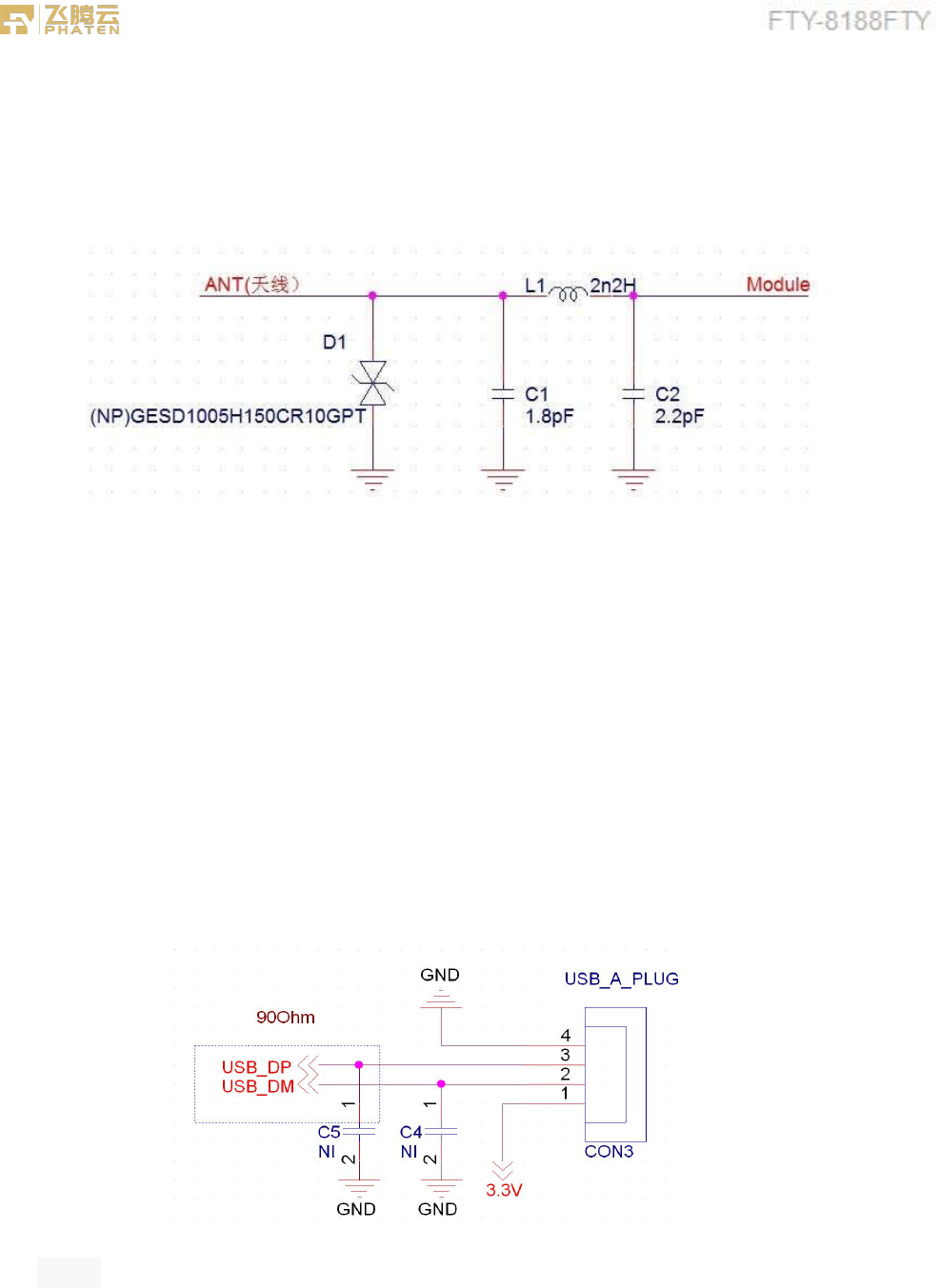
5.1WIFI RF Circuit reference pictures
1.
Above the dotted box part of the antenna matching is needed,
the actual antenna matching electronic parameters shall
prevail.
2. For RF part layout to do 50 ohm impedance. can't go on 90
°
of
layout .The line
length can't more than20 mm.
Note: Please be sure to add a TVS tube at the end of the welding antenna to prevent ESD static
electricity from damaging the WIFI module (as shown in the reference circuit above).
5.2 USB interface electrical characteristics
Note:
1.USB data cable need to do 90Ohm impedance
2.It is recommended to keep a power switch at the input end of the power supply. Each
time the card is opened or closed, it can be used for power on and power off. WIFI can
be reset, so that there will be no error phenomenon of not opening WIFI.