
Data Sheet

FSC‐BT630Datasheet
ShenzhenFeasycomTechnologyCo.,Ltdwww.feasycom.com
‐13‐
corruptioniftwoormoremastersattempttocontrolthebussimultaneously.
DataistransferredbetweenaMasterandaSlavesynchronouslytoSCLontheSDAlineonabyte‐by‐bytebasis.Each
data byte is 8‐bit long. There is one SCL clock pulse for each data bit
with the MSB being transmitted first. An
acknowledgebitfollowseachtransferredbyte.EachbitissampledduringthehighperiodofSCL;therefore,theSDA
line may be changed only during the low period of SCL and must be held stable during the high period of SCL. A
transition
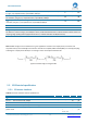
ontheSDAlinewhileSCLishighisinterpretedasacommand(STARTorSTOP).Pleaserefertothefollowing
figureformoredetailsaboutI2CBusTiming.
Thedeviceon‐chipI2ClogicprovidestheserialinterfacethatmeetstheI2Cbusstandardmodespecification.TheI2C
porthandlesbyte transfersautonomously.The I2CH/Winterfacestothe I2Cbusvia twopins:SDA andSCL.Pull up
resistorisneededforI2Coperationastheseareopendrainpins.WhentheI/OpinsareusedasI2Cport,usermustset
thepinsfunctiontoI2Cinadvance.
TheI2CmasteriscompatiblewithI2Coperatingat100kHzand400kHz.
4.9Pulsewidthmodulation(PWM)
ThePWMmoduleenablesthegenerationofpulsewidthmodulatedsignalsonGPIO.Themodule implementsanupor
up‐and‐downcounterwithfourPWMchannelsthatdriveassignedGPIOs.
Three PWM modules can provide up to 12 PWM channels with individual frequency control in groups of up to four
channels. Furthermore, a built‐in decoder and EasyDMA capabilities make it possible to manipulate the PWM duty
cycles without CPU intervention. Arbitrary duty‐cycle sequences are read from Data RAM and can be chained to
implementping‐pongbufferingorrepeatedintocomplexloops.
Listedherearethemainfeatures
ofonePWMmodule:
FixedPWMbasefrequencywithprogrammableclockdivider
UptofourPWMchannelswithindividualpolarityandduty‐cyclevalues
Edgeorcenter‐alignedpulsesacrossPWMchannels
Multipleduty‐cyclearrays(sequences)definedinDataRAM
Autonomousandglitch‐freeupdateofdutycyclevaluesdirectlyfrommemorythroughEasyDMA
Changeofpolarity,duty‐cycle,andbasefrequencypossiblyoneveryPWMperiod
DataRAMsequencescanberepeatedorconnectedintoloops
4.10Pulsedensitymodulationinterface(PDM)
The pulse density modulation (PDM) module enables input of pulse density modulated signals from external audio
frontends,forexample,digitalmicrophones.ThePDMmodulegeneratesthePDMclockandsupportssingle‐channelor
dual‐channel(LeftandRight)datainput.DataistransferreddirectlytoRAMbuffersusingEasyDMA.
Listedhere
arethemainfeaturesforPDM:
UptotwoPDMmicrophonesconfiguredasaLeft/Rightpairusingthesamedatainput
16kHzoutputsamplerate,16‐bitsamples
EasyDMAsupportforsamplebuffering