
User's Manual

APN0000236_V0.3.1_UDL07XX_User Manual_Lora 20220728 Final Document level: 2
Doc.#: #: APN0000236_V0.3.1_UDL07XX_User Manual_Lora 20220728 Final
Page 14 of 22
This Record Storage Period: Permanent
Black
Pin 5
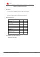
RS485 Cable:
Cable Color
Signal definition
Red
RS485(A)
Black
RS485(B)
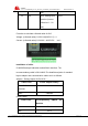
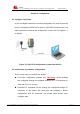
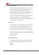
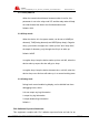
Power adapter and communication cable connection chart is as follows:
2.4 Power
The power range of the Lora is DC 5~36V.
Warning: When we use other power, we should make sure that the power
can supply power above 4W.
We recommend user to use the standard DC 12V/0.5A power.
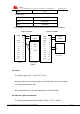
2.5 Indicator Lights Introduction
The Lora provides three indicator lights: “Power”, “ACT”, “Online”.
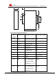
F8L10T
F8L10T
User Device
(DB9M)
User Device
1
2
3
4
5
6
7
8
9
10
11
12
RX
GND
TX
A
B
IO1
IO2
IO3
IO4
PWR
GND
IO5
1
2
3
4
5
6
7
8
9
GND
TX
RX
+ Anode
- Cathode
RX
1
2
3
4
5
6
7
8
9
10
11
12
RX
GND
TX
A
B
IO1
IO2
IO3
IO4
PWR
GND
IO5
+ Anode
- Cathode
A
B
Connect via RS232
Connect via RS485