
User's Manual

SK202 User manual 5 of 7
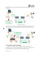
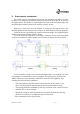
5. Environment constraints
For the RF waves to propagate correctly from one module to the other, care must
be taken not to introduce any metallic obstacle in a Keep Out Area (KOA), in green on
the figures below. This KOA is a parallelepiped of 22 mm width and 9 mm height. The
length being the distance between the antennae, usually 30 mm.
Moreover, a Safe Area has been defined, in orange on the figures below. The
elements present in this area may have an impact on the millimeter waves propagation.
This Safe Area is a parallelepiped of 60 mm width and height. The length being the
distance between the antennae, usually 20 mm.
In case an electronic component, a metal part, a fastener, a screw, some metal paint
or any sort of reflective surface resides in this volume, its impact must be analyzed.
Figure 8. Keep Out Area (Green) and Safe Area (Orange)
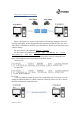
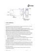
In case a metallic casing is to be used around the modules, it is mandatory to insert
an opening for the millimeter waves to propagate. This opening may be filled with
ABS or other microwave insensitive materials to maintain water tightness. This
opening should follow these guidelines:
• The casing must be placed at around 2.7mm from the PCB to ensure a free
space of 0.8mm between the Horn antennae body and the ABS housing.
• The opening should be minimum 22 mm long and 9 mm wide, centered on the 2
antennae, but it can be enlarged.
• Should the casing be placed further than 2.7mm from the PCB, the opening
dimensions will have to be adjusted to prevent reflections.
This is summarized in the figure below: