
Service manual


www.enc.net.cn/en Tel/Fax:86-755-26984485/26985120 11 Modbus communication protocol
128
11 Modbus communication protocol
11.1 Summarization
We provide general RS485 communication interface in our inverters (such as
EDS800 series, EDS1000 series and etc.) for the user. Through this
communication interface upper device (such as HMI, PC, PLC controller and etc.)
can perform centralized monitor to the inverter (such as to set inverter parameter,
control run of inverter, read work state of the inverter).
This communication protocol is interface criterion file designed for realizing
above-mentioned function, please read it earnestly and program according to it so
that realize long-distance and network control to the inverter.
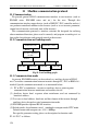
11.2 Communication net buildup mode
Fig.11-1 net buildup graph
11.3 Communication mode
At present, EDS1000 inverter can be used only as auxiliary device in RS485
net. Can realize communication between inverters through PC, PLC or HMI if it’s
needed. Specific communication mode is as mentioned below:
(1) PC or PLC as mainframe,inverter as auxiliary device, point-to-point
communication between mainframe and auxiliary device.
(2) Auxiliary device don’t response when mainframe send out command by
broadcast address.
(3) User can set local address, baud rate and data format of the inverter through
auxiliary device keypad or serial communication mode.
(4) EDS1000 provides optional RS485 interface.
(5) Default mode: Asynchronous serial,semiduplex transport mode. RTU mode.
Default format and transport rate: 8-N-1, 9600bps.
For specific parameter setting please see description for function code
F2.14~F2.17 as follows:
EDS1000 EDS1000 EDS800 EDS800
mainframe is PC
mainframe is PLC
232-485 conversion
module
or
RS232
RS485