
Service manual


www.enc.net.cn/en Tel/Fax:86-755-26984485/26985120 10 Examples
127
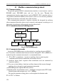
(2) Basic wiring diagram
Fig.10-10 basic wiring diagram for constant pressure
water supply controller
Description:
(1B,C1B), (1G,C1G), (2B,C2B), (2G,C2G), (3B,C3B), (3G,C3G), (4B,C4B),
(4G,C4G) denote respectively 2 terminals corresponding to control terminal“No.1
variable frequency”, “No.1 bypass”, “ No.2 variable frequency”, “ No.2 bypass”,
“ No.3 variable frequency”, “ No.3 bypass”, “ No.4 variable frequency”, “ No.4
bypass” on constant pressure water supply controller.
KM0
1B
C1B
1G
C1G
2B
C2B
2G
C2G
3B
C3B
3G
C3G C3G
4B
C4B
4G
C4G
KM1
KM2
KM3
KM4
KM5
KM6
KM7
KM7
KM6
KM5 KM4 KM3 KM2 KM1
KM0
FR1
FR2
FR3 FR4
KM6
KM4
KM2
KM1
KM6
KM4
KM0
KM3
KM0
KM2
KM6
KM2
KM0
KM5
KM4
KM4
KM2
KM0
KM7
KM6
KM0
KM1
KM2
KM3
KM4
KM5
KM6
KM7
FR1
FR2
FR3
FR4
M4-3
M1-3
M2-3
M3-3
3 phase breake
r
3 phase breake
r
2 phase breake
r
L1
L2
L3
N
inverter
Constant pressure
Water su
pp
l
y
controlle
r
(1) Should apply AC contactor with mechnical interlock between inverter output
andpower source bypass beside the motor, and perform logic interlock in electric
control loop to avoid short circuit between inverter output and power source which
will damage the inverter and interrelated device;
(2) Phase order of power source L1,L2,L3 connected with the motor should be the same
as that of inverter output U, V, W,please operate after confirm with phase order
table to avoid motor reverse run caused during converted frequency/ power source
switch.
(3) There should be over current protection device in power source bypass to the motor.
!