
Service manual


www.enc.net.cn/en Tel/Fax:86-755-26984485/26985120 6 Detailed function description
97
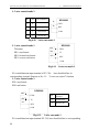
Fig.6-33 swing freq. range restriction Fig.6-34 freq. arriving signal output
17: Interior counter reach final value
18: Interior counter reach specified value
17~18 please refer to function description of F5.25~F5.26.
19: Set runtime arrive. When accumulative runtime of the inverter (F2.52)
reach set runtime(F2.51),output indicator signal.
20: Interior timing arrive. Refer to function description for F5.27.
21: OC1- variable Freq. for the 1
st
pump
OC2- power source for the 1
st
pump
OC3- variable Freq. for the 2
nd
pump
OC4- power source for the 2
nd
pump
22: Reserved
23: Reserved
24: Reserved
F5.14 Freq. arriving(FAR)detect range
Range: 0.00-50.00Hz
5.00Hz
This parameter is supplementary definition to No. 1 function in Table 6-8.As
shown in Fig.6-34,when output frequency of the inverter is within high&low
detect range of set frequency,output pulse signal.
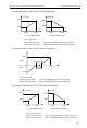
F5.15
FDT1(freq. level) electric level
Range: 0.00-high
limit frequency
10.00Hz
F5.16
FDT1 lag Range: 0.00-50.00Hz
1.00Hz
F5.15~F5.16 is supplementary
definition to No.2 function in Table
6-8, introduce as follows: When
output frequency exceed the set
frequency(FDT1 electric level) ,
output indicator signal , till output
frequency descend to be some
frequency(FDT1 electric level-FDT1
lag) lower than FDT1 electric level,
as shown in Fig.6-35.
Y1: swing freq.
fluctuation
Low limit
High limit
output
Set
Freq.
time
time
Y
checkout range
Output freq.
FDT1 electric
level
time
time
Y
FDT1 lag
Fig.6-35 freq. level detecting