
Service manual


www.enc.net.cn/en Tel/Fax:86-755-26984485/26985120 6 Detailed function description
96
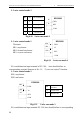
Now introduce function listed in Table 6-8 as follows:
0: inverter during running(RUN). The inverter is in run status,output
indicator signal.
1: frequency arriving signal(FAR). Refer to function description of F5.14.
2: Frequency level detecting signal(FDT1). Refer to function description of
F5.15~F5.16.
3: reserved
4: overload warning signal(OL)
. Inverter output current exceed F9.05
overload detect level and time exceed F9.06 overload detect time,output indicator
signal.
5: output frequency reach high limit(FHL). When set frequency≥high
limit frequency and run frequency reach high limit frequency,output indicator
signal.
6: output frequency reach low limit(FLL). When set frequency≤low limit
frequency and run frequency reach low limit frequency,output indicator signal.
7: Inverter stops for under voltage blockage(LU). When the inverter
is running, LED displays“P. OF F ”and output indicator signal if DC bus-bar
voltage is lower than limitative level.
8: stop for exterior failure(EXT). When the inverter give the alarm (E014)
and stops for exterior failure, output indicator signal.
9: inverter zero rotate speed running. When the inverter output zero
frequency but in run status, output indicator signal.
10: PLC running
11: Simple PLC segment running finished. After simple PLC current
segmentrun is finished,output indicator signal(single pulse signal,width 500ms).
12: PLC finish one cycle run
13: reserved
14: Inverter ready to run(RDY). If this signal is effective, shows
that bus-bar voltage is normal and run prohibition terminal is ineffective, the
inverter can receive start-up command.
15: Inverter fault. If failure takes place when the inverter is running, the
inverter output indicator signal.
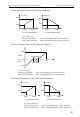
16: Swing freq. high&low limit restriction. After choosing swing frequency
function, if frequency fluctuant range based on center frequency of swing
frequency is above high limit frequency F0.10 or under low limit frequency F0.11,
the inverter will output indicator signal, as shown in Fig. 6-33.