
Service manual


www.enc.net.cn/en Tel/Fax:86-755-26984485/26985120 6 Detailed function description
95
terminal function as No. 19 “3-wire run control” function.
The inverter restores after failure and start at once if run command channel
selecting terminal and terminal FWD/REV is effective during warning alarm stop.
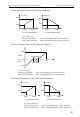
F5.09 UP/DOWN velocity Range: 0.01-99.99Hz/S 1.00Hz/S
This function code defines varying rate of the set frequency when it’s modified
by UP/DOWN terminal.
F5.10
Open circuit collector output
terminal OC1 out
p
ut settin
g
Range: 0~24 0
F5.11
Open circuit collector output
terminal OC2 output setting
Range: 0~24 4
F5.12
Open circuit collector output
terminal OC3 output setting
Range: 0~24 5
F5.13
Open circuit collector output
terminal OC4 output setting
Range: 0~24 18
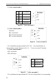
OC1~OC4 open collector output terminal,Table 6-8 shows option of above 4
function parameter,choosing same output terminal function repeatedly is allowed.
Table 6-8 output terminal function selection table
Item Corresponding function Item Corresponding function
0 Inverter running signal (RUN) 1 Frequency arriving signal (FAR)
2
Frequency level detecting
signal (FDT1)
3 Reserved
4 Overload warning signal(OL) 5 Output Freq. reach high limit(FHL)
6 Output Freq. reach low limit(FLL) 7
Inverter stop for under voltage
blockage (LU)
8 Stop for exterior failure(EXT) 9 Inverter zero rotate speed running
10 PLC running 11 Simple PLC segment run finished
12 PLC finish one cycle run 13 Reserved
14 Inverter ready to run(RDY) 15 Inverter failure
16
Swing Freq. high&low limit
restriction
17 Interior counter final value arrive
18
Interior counter specified value
arrive
19 Set runtime arrive
20 Interior timer timing arrive 21
OC1- variable Freq. for the 1
st
pump
OC2- power source for the 1
st
pump
OC3- variable Freq. for the 2
nd
pump
OC4- power source for the 2
nd
pump
22 Reserved 23 Reserved
24 Reserved