
User's Manual
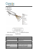


Table Of Contents

Table 1
Line
Color
Definition
Description
1
Red
PW+
12V/24V positive side of battery
2
Black
GND
12V/24V negative side of battery
3
Orange
ACC
ACC ignition
4
Yellow
RELAY
Relay
5
Red
5V-OUT
External power supply
6
Blue
RX
Data receiving / backup interface
7
Green
TX
Data sending/ backup interface
8
Black
GND
Negative electrode
9
Purple
ADC
Extended Interface
10
Orange
IN1
11
Yellow
OUT1
12
Black
GND
SOS button
13
Orange
SOS+
14
Brown
MIC+
Microphone
15
Black
MIC-
Relay wiring instruction
Relay wiring way of oil pump open circuit: On each end of the wire is thin white
line (85) and thin yellow line (86). Thin white line (85) connects to the positive
side of battery (12V) while thin yellow line (86) connects to the device relay
control. There is an oil pump in the vehicl. Cut off the positive line. The positive
side of oil pump connects to the close-end of relay.(Thick green line 87a), and