3G GPS Vehicle tracker (GPS+WCDMA+SMS) User Manual (Version 1.0) This user manual has been specially designed to guide you through the functions and features of your GPS vehicle tracker.
1. Start Guide 1.1 Accessories: Device Power cord Relay (Optional) Microphone SOS alarm cable & button User Manual 1.2 Main Functions Real-time tracking Vibration/Displacement/Low battery/Power off alert SOS ACC detection Geo-fence Mileage Air update AGPS locating Remotely control electricity/oil Analogue input Output control Digital input 1.
2 My device 2.1 Appearance 2.2 LED indicators GPS LED Indicator - Blue Flashing (interval 0.1s) Solid blue OFF GSM LED Indicator - Green Quick flashing (interval 0.1s) Slow flashing (flash 0.
Power Status - Red Flashing (interval 0.1s) Slow flashing (interval 2s) Slow flashing (flash 0.1s off 2s) Solid Red OFF Low battery Full charge Normal operating Charging Low battery/Power off Note: Defense Status The device is in defense status if blue, red and green indicator flashed in a loop. 3. Installation 3.1 Install the SIM card Notice: SIM should be inserted correctly. SIM card should have GPRS service.
3.
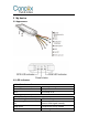
Table 1 Line 1 2 3 4 5 6 7 8 9 10 11 12 13 14 15 Color Red Black Orange Yellow Red Blue Green Black Purple Orange Yellow Black Orange Brown Black Definition PW+ GND ACC RELAY 5V-OUT RX TX GND ADC IN1 OUT1 GND SOS+ MIC+ MIC- Description 12V/24V positive side of battery 12V/24V negative side of battery ACC ignition Relay External power supply Data receiving / backup interface Data sending/ backup interface Negative electrode Extended Interface SOS button Microphone Relay wiring instruction Relay wiring wa
the other side connects to relay’s common(green thick 30). Notice: 12V relay is standard. The device is suiitable for vehicles with 12V battery. If the vehicle has 24V battery, then 24V relay needed. 3.
1) The standard power supply ranges from 9V to 36VDC. Please use the powe cord manufactured by the original factory. Red line means positive side while black line means negative side. During installation, negative side should connect to the ground.
flamout. 3) Device’s oil and electricity control line (yellow) connects to relay’s 86. (thin yellow line of relay socket) 3.4 Device Installation Note: The device should face up to the sky Metal thermal barrier or heating layer of the windshield affects the signal. Please change installation places to receive better signal. 4.
5. Main Functions 5.1 SOS In emergent case, press SOS for 3s to activate SOS alarm. Then the device will send SOS SMS to preset SOS numbers and then dial the numbers in 3 circles until the call is picked up. Alarm message will also send to platform. 5.2 Power cut-off alarm When the electricity supply of device is cut off, it will activate cut-off alarm. 5.3 Low battery alarm When battery is low, the device will activate low battery alarm. 5.
1. 2. 3. 4. Make sure ACC is correctly connected. When ACC is OFF, command will be executed immediately. When ACC is ON, but GPS is not fixed, command will be postponed. When ACC is ON, GPS is fixed, command will be executed when vehicle speed is less than 20km/h. 5.8 Restore oil/electricity When alarm is cancelled, user can send restore oil/electricity command by platform, APP or SMS and restore vehicle power. 5.
3 Check device location in Google Map link 4 SOS number setting 5 GPS data upload time interval 6 7 GPS data upload distance interval Delayed defense setting 8 URL# 1, Add SOS number: SOS,A,number 1,number 2,number 3# Example: SOS,A,12342***,134533***,135432***# 2, Delete subjected sequence of SOS number: SOS,D,number sequence 1,number sequence 2, number sequence 3# Example: SOS,D,1,2# 3, Delete the SOS number: SOS,D,phone number# 4, Query SOS number: SOS# TIMER,T1,T2# T1=5~18000 seconds;ACC ON up
If you are having trouble with your device, try these troubleshooting procedures before contacting a service professional.
Warranty instructions and service 1. The warranty is valid only when the warranty card is properly completed, and upon presentation of the proof of purchase consisting of original invoice indicating the date of purchase, model and serial No.of the product. We reserve the right to refuse warranty if this information has been removed or changed after the original purchase of the product from the dealer. 2.
FCC Statement 1. This device complies with Part 15 of the FCC Rules. Operation is subject to the following two conditions: (1) This device may not cause harmful interference. (2) This device must accept any interference received, including interference that may cause undesired operation. 2. Changes or modifications not expressly approved by the party responsible for compliance could void the user's authority to operate the equipment.