M400 USER MANUAL Trademarks Input Manually or Scan HUMZOR®, NEXZDAS®, th^M400®, and NEXZSCAN® are trademarks of Shenzhen Hanzhi QR C* Technology Co., Ltd., registered in China, the United States and other countries. All other marks are trademarks or registered trademarks of their respective holders.
For details, please refer to the Service Procedures in this manual Safety Information For your own safety and the safety of others, and to prevent damage to the device and vehicles upon which it is used, it is important that the safety instructions presented throughout this manual be read and understood by all persons operating or coming into contact with the device. There are various procedures, techniques, tools, and parts for servicing vehicles, as well as in the skill of the person doing the work.
SAFETY WARNINGS Always perform automotive testing in a safe environment. • Wear safety eye protection that meets ANSI standards. • Keep clothing, hair, hands, tools, test equipment, etc. away from all moving or hot engine parts. • Operate the vehicle in a well-ventilated work area, for exhaust gases are poisonous. • Put the transmission in PARK (for automatic transmission) or NEUTRAL (for manual transmission) and make sure the parking brake is engaged.
1.Using This Manual This manual contains device usage instructions. Some illustrations shown in this manual may contain modules and optional equipment that are not included in your system. 1.1Conventions The following conventions are used. 1.1.1Bold Text Bold text is used to highlight selectable items such as buttons and menu options. • Tap NEXT 1.1.2Notes and Important Messages A NOTE provides helpful information such as additional explanations, tips, and comments.
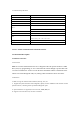
• M400 Tablet - the central processor and monitor for the system. • M400 VCI - Vehicle Communication and Check Interface. This manual describes the construction and operation of these devices and how they work together to deliver diagnostic solutions. 2.1Tablet 2.1.1Functional Description 4.0 inch LCD Capacitive Touchscreen Type-C charging port Volume button for up and down Reset button for restart tablet Power button 2.1.
2.1.3Technical Specifications Name Specifications LCD LCD:4.0 inch WVGA(480*800) Frequency GSM、WCDMA、LTE:Not required T card Support single T card,Support up to 32GB Flash size EMCP 8GB+1GB LP DDR3 or EMCP 4GB+512M LP DDR3 2.4 GHz,support 802.
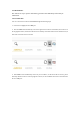
2.3.3Performance The software is easy to operate and reliable, guarantees the authenticity and security of information. 3.VCI Connection You can connect the VCI device with M400 through the following steps: 1. Insert the VCI tightly into the OBD port. 2. Then the M400 will automatically scan and recognize the VCI device. At this time, the VCI icon on the top right turns blue, which means the VCI is successfully connected. If the VCI icon still shows red, it means the connection is not successful. 3.
4.Diagnostics 1. Support 91 car brands: American cars (15), European cars (34), Asian cars (16), Chinese cars (24), Australian cars (2). 2. Support more than 100 special functions,external 9 kinds of common special functions. 4.1Protocol Supported High Speed CAN - offers baud rates from 40 Kbit/s to 1 Mbit/sec, depending on cable length. This is the most popular standard for the physical layer, since it allows for simple cable connection between devices.
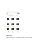
4.2.1Vehicle Menu Layout For example: Click on DAS->EUROPE Manufacturer Buttons The Manufacturer buttons display the various vehicle brand names. Select the manufacturer button after the VCI device is properly connected to the test vehicle to start diagnostic session. Select EUROPE->BMW brand to check.
4.2.2Vehicle Identification The M400 diagnostic system supports two methods ofVehicle Identification. 1. Vehicle Manual Select 2.
4.2.2.1Vehicle Manual Select For vehicles that do not support the Auto VIN diagnose function, the M400 diagnostic system allows you to enter the vehicle brand manually. 4.2.2.2Vehicle Select by VIN The M400 diagnostic system features the latest VIN-based Auto VIN Scan function to identify CAN vehicles with just one tap, enabling the technician to quickly identify the exact vehicle and scan its available systems for fault codes.
After the vehicle information is selected. Tap the NEXT button at the bottom right corner of the screen to open the Main menu page. This section consists of various functions commonly used, including test, systen selection, and more. The available functions displayed vary by vehicle.
4.2.3 Quick Test The Quick Test function performs a comprehensive scanning of all the systems in the vehicles ECVU to locate faults and retrieve DTCs. Tap Fault to start. Sytems with no faults detected will display√; systems containing faults will display the numbers of the faults, such as DTC(2).
4.2.4 Control Unit This option allows you to manually locate a required control system for testing through a series of choices. Simply follow the menu driven procedure, and make proper selection each time; the program will guide you to the diagnostic function menu after a few choices you've made. Available functions may vary by vehicle. The function menu may include: System information - displays detailed ECU information. Select to display information screen.
from the ECU. • Live data - retrieves and displays live data and parameters from the vehicle's ECU. • Active test - provides specific subsystem and component tests. This selection may display as Actuators, Actuator Test, or Function Tests. Available tests vary by vehicle. • Special functions - provides component adaptation or variant coding functions for custom configurations, and allows entry of adaptive values for certain component after repairs.
Freeze Frame - icon displays when freeze frame data is available for viewing; Tap icon to display data screen. The Freeze Frame interface is similarto that of the Read DTCs interface and share similar operations. Search - tap to serach the selected DTC for additional information on the internet. Clear DTCs - tap to erase codes from the ECU. It is recommended that DTCs are read and needed repairs are performed before erasing codes. Read DTCs - retrieves and displays the DTCs from the vehicle control system.
To perform Manual Input 1. Tap Clear Codes in the Function Menu. 2. A warning message displays to inform you of data loss when this function is applied. a) Tap YES to continue. A confirming screen displays when the operation is successfully done. b) Tap NO to exit. 3. Tap ESC on the confirming screen to exit Erase Codes. Check the Read Codes function again to ensure the operation is successful.
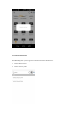
4.2.7 Read Data Stream When this function is selected, the screen displays the data list for the selected module. The parameters display in the order that they are transmitted by the ECU, so expect variation amongvehicles. Gesture scrolling allows you to quickly move through the data list. Touch the screen and drag your finger up or down to reposition the parameters being displayed if the data occupies more than one screen. The figure below displays a typical Live Data screen: 4.2.
The functional buttons in the lower right corner of the Active Test screen manipulate the test signals. The operational instructions are displayed in the main section of the test screen. Follow the on-screen instructions and make appropriate selections to complete the tests. Tap the ESC functional button to exit the test when finished. 5.
6.Me On the "HUMZOR" main interface, click the "Me" icon button, and the system will guide you to the interface. 6.1Unit In the Settings interface, click the "Units" button to switch the units. 6.2Upgrade If your M400 application is not the latest version, you can upgrade the application version through the following steps: 1. On the Me interface, click the "Upgrade" icon button.
2. Click the "Download" button on the right to start downloading the new version. 3. The version is downloaded successfully, click the "INSTALL" button to start the installation. 4. The version is downloaded successfully, click the "INSTALL" button to start the installation. 6.3Settings On the "M400" main interface, click the "Settings" icon button, and the system will guide you to the Settings interface. 6.3.1System Info Click System Info and you can view the information of the application. 6.3.
The buttons on the navigation bar from left to right are Reset connection VCI, Screenshots, Bluetooth connection. 7.1Reset connection VCI Open the home page of the app, click the first icon on the top right. Click OK to reset connection VCI. Then please wait for the initialization of VCI. After that, the VCI will be successfully reset. 7.