
User's Manual
36882 English I/B ver. 11202A-1
11
11202A-1
OWNER’S MANUAL
# 36882
ver.
11202A-1
Page : 11 ENGLISH VERSION
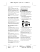
(Figure 2)
Wall Mounting (With a standard AT&T
or GTE modular wall jack)
You may choose to install the Telephone
base unit onto a wall.
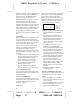
Wall Mounting (Standard Wall Jack)
1. Connect the short telephone line cord to
the telephone line jack on the rear of the
base unit.
2. Insert the free end of the short line cord
through the hole of the mounting
bracket.
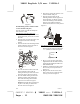
3. Insert the hooks of the mounting bracket
into the matching slots on the back of
the unit as shown in Figure 3.
4. Press the two locks located on the side
of the mounting bracket until the
locking hooks snaps into the inner slots
of the base unit as shown in Figure 4.
5. Press the middle locking hooks of the
mounting bracket while pushing the
back of the mounting bracket until it
snaps to lock as shown in Figure 5.
NOTE: Ensure that the lock guide stays
in place on the hole provided on the
base unit as shown in Figure 6.
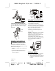
6. Plug the free end of the short line cord
into the modular wall jack.
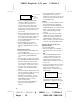
7. Align the upper keyhole on the
mounting bracket with the upper stud
of the wall plate, so that the opening
end of the mounting bracket matches
the lower stud, pull the mounting
bracket down until it is securely seated.
(Figure 7)
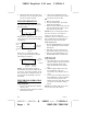
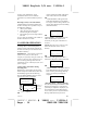
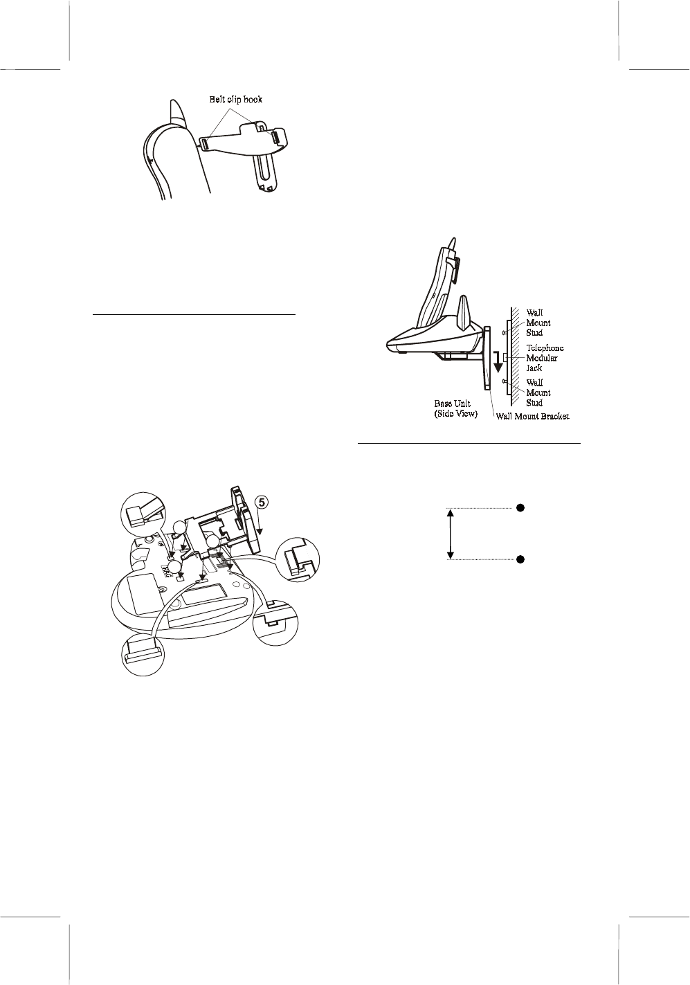
Wall Mounting (No Standard Wall Jack)
1. Drill two holes with a vertical distance
between the two marked positions of 3
15/16
" (100mm) as shown in Figure 8.
3
15/16
"
(100mm)
(Figure 8)
2. Drive a screw into each of the holes.
Tighten them to the end of the screw lines,
only leaving the smooth part of the screw
head outside the wall.
3. Install the wall mount bracket into the
base unit as previously discussed in
Figures 3-6.
4. Hang the unit onto the screws, then
slide it down
firmly
to fasten the base
securely, as shown in Figure 9.
Figure 3
Figure 6
Figure 4
3
Figure 5
5
4
H
I
M
ID
L
O
W