
User's Manual


www.art-tech.com
11
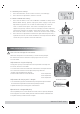
6.3 Auxiliary trim settings:
1. Press the sub button; enter into the Trm menu (Trim Settings).
2. Press the Left or right button, choose a channel.
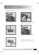
6.4 Mode I and Mode II setting:
1. Press the sub button, enter into the Mode I and Mode II setting menu.
Before Mode Setting, please unplug the power supply of the plane.
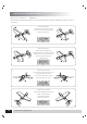
Adjustment of joysticks The screws for mode setting are in the rear
cover. as shown in the figure: The screws A and B play the role of
suppressing springs; and the screws C and D play the role of adjusting
resist force. Therefore, for mode I, loosen the screws A and C, tighten
the screws B and D. For mode II, loosen the screws B and D, tighten
2. Press the Left or right button to choose the right mode and press the y /
up button to confirm. Left stands for Mode II, while right stands for Mode
I. After that you can process Channel calibration.
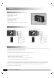
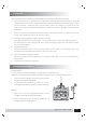
Alarm for low voltage of transmitter
Other function of the transmitter
When the voltage of transmitter battery is under working voltage,
the red LED will flash.It is better to stop flying,or that can cause
crash of model.
Operation for chargeable plug
The chargeable plus is on the side of transmitter,and it is specially designed
for charging the transmitter battery.Please note the batteries should be well
arranged in the bay and do not over charged
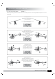
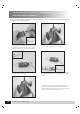
Adjustment for the joystick`s length
1.turn the head of joystick anticlockwise to prolong the length and deasil
for shorten the length Please note do not prolong too much.
2.tighten the lower part of the joystick anticlockwise
Deasil to short
Anticlock to prdory
Adjustment on Joystick Spring
The joystick spring can be adjusted and it is possible to change that
for ailoren, elevator and rudder.
1.Turn the srew on the transmitter back anticlockwise, and open the back
2.turn the screw of the channel to adjust the spring, deasil for
stronger and anticlockwise for weaker.
3.close the back and turn the screw deasil
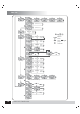
screw adjustment
screw adjustment
screw adjustment
C
A
B
D